Advertisements
Advertisements
प्रश्न
Define capacitive reactance.
उत्तर
The capacitive reactance of a capacitor is defined as the ratio of r.m.s voltage (e.m.f) across the capacitor to the corresponding r.m.s current.
APPEARS IN
संबंधित प्रश्न
Choose the correct option.
In a circuit L, C and R are connected in series with an alternating voltage of frequency f. the current leads the voltage by 45°. The value of C is ______.
In an AC circuit, e and i are given by e = 150 sin(150t)V and i = 150 sin `(150t + π/3)` A. The power dissipated in the circuit is ______.
An electric lamp is connected in series with a capacitor and an AC source is glowing with a certain brightness. How does the brightness of the lamp change on increasing the capacitance?
An electric current in an LC – circuit at resonance is called - ______
If AC voltage is applied to a pure capacitor, then the voltage across the capacitor ______
An electric bulb operates 10 V d.c. If this bulb is connected to an a.c. source and gives normal brightness, then the peak value of the source is ______
State the equation for impedance Z in an A.C. circuit.
Explain term impedance and state the formula for it in the case of an LCR series circuit.
Find the current in a circuit consisting of a coil and a capacitor in series with an A.C source of 110V (r.m.s.), 60Hz. The inductance of a coil is 0.80 H and its resistance is 50Ω. The capacitance of a capacitor is 8µF.
A 0.5µF capacitor is discharged through a 10 millihenry inductor. Find the frequency of discharge.
What is the capacitive reactance of a capacitor of 5µF at a frequency of (1) 50 Hz and (2) 20KHZ?
What is the inductive reactance of a coil of inductance 10mH at a frequency
- 50 Hz
- 1000 Hz
- 20 kHz?
Explain the term inductive reactance. State its unit and dimensions.
Obtain the expression for the applied emf and the effective resistance of the circuit when alternating emf is applied to an LR circuit.
Obtain the expression for the applied emf and the effective resistance of the circuit when alternating emf is applied to a CR circuit.
The standard voltage of A.C. mains in India is ______
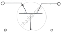
For circuit shown in figure IE = 4 mA, IB = 40 µA. What are the values of ex, and le respectively?

In amplitude modulation. the amplitude of carrier wave is Ac and that of the modulating signal is Am· In practice, the ratio of Am to Ac is kept less than or equal to one, to avoid ______.
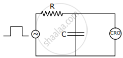
An RC Circuit as shown in the figure is driven by a AC source generating a square wave. The output wave pattern monitored by CRO would look close to:

