Advertisements
Advertisements
प्रश्न
उत्तर
Experiment 1
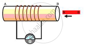
(i) Take a coil of wire AB having a large number of turns.
(ii ) Connect the ends of the coil to a galvanometer as shown in figure.
(iii ) Take a strong bar magnet and move i ts north pole towards the end B of the coil.
(iv) There is a momentary deflection in the needle of the galvanometer, say to the right. This indicates the presence of a current in the coil AB. The deflection becomes zero the moment the motion of the magnet stops.
(v) Now withdraw the north pole of the magnet away from the coil. Now the galvanometer is deflected toward the left, showing that th e current is now set up in the direction opposi te to the first.
(vi) Place the magnet stationary at a point near to the coil, keeping i ts north pole towards the end B of the coil. We see that the galvanometer needle deflects toward the right when the coil is moved towards the north pole of the magnet. Similarly the needle moves toward left when the coil is moved away.
(v) When the coil is kept stationary with respect to the magnet, the deflection of the galvanometer drops to zero.

Experiment 2
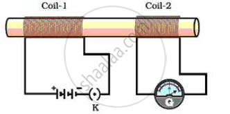
(i) Take two different coils of copper wire having large number of turns (say 50 and 100 turns respectively). Insert them over a non -conducting cylindrical roll, as shown in figure.
(ii ) Connect the coil -1, having larger number of turns, in series with a battery and a plug key. Also connect th e other coil -2 with a galvanometer as shown .
(iii ) Plug in the key. Observe the galvanometer. We will observe that the needle of the galvanometer instantly jumps to one side and just as quickly returns to zero, indicating a momentary current in coil -2.
(iv) Disconnect coil -1 from the battery. We will observe that the needle
momentarily moves, but to the opposi te side. It means that now the current flows in the opposi te direction in coil -2.

From these observations, we conclude that a potential difference is induced in the coil -2 whenever the electric current through the coil - 1 is changing (starting or stopping). This process, by which a changing magnetic field in a conductor induces a current in another conductor, is called electromagnetic induction.
To determine the direction of induced current, we use Fleming's left hand rule:
Stretch the thumb, forefinger and middle finger of right hand so that they are perpendicular to each other. If the forefinger indicates the direction of the magnetic field and the thumb shows the direction of motion of conductor, then the middle finger will show the direction of induced current.
Magnitude of induced current can be measured wi th the help of a galvanometer.
APPEARS IN
संबंधित प्रश्न
Which instrument is used to measure electric current? How should it be connected in a circuit?
(a) With the help of a circuit diagram, obtain the relation for the equivalent resistance of two resistances connected in parallel.
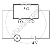
(b) In the circuit diagram shown below, find:
(i) Total resistance.
(ii) Current shown by the ammeter A

What happens to the other bulbs in a series circuit if one bulb blows off?
Draw a circuit diagram to show how two 4 V electric lamps can be lit brightly from two 2 V cells.
The following table shows the current in Amperes and potential differences in Volts.
- Find the average resistance.
- What will be the nature of the graph between the current and potential difference? (Do not draw a graph.)
- Which law will the graph prove? Explain the law.
| V (volts) | I (amp) |
| 4 | 9 |
| 5 | 11.25 |
| 6 | 13.5 |
60 joules of heat was dissipated in a resistor when 20 C flowed for 5 s. Calculate:
(a) P.d. across the resistor,
(b) Resistance of the resistor, and
(c) Average power dissipated in the resistor.
A bulb is connected to a battery of p.d. 4 V and internal resistance 2.5 Ω . A steady current of 0.5 A flows through the circuit. Calculate:
The resistance of the bulb
State the condition when it is advantageous to connect cells in parallel.
