Advertisements
Advertisements
प्रश्न
Draw the circuit diagram of a half wave rectifier and explain its working.
उत्तर
The half-wave rectifier circuit. The circuit consists of a transformer, a p-n junction diode and a resistor. In a half-wave rectifier circuit, either a positive half or the negative half of the AC input is passed through while the other half is blocked. Only one-half of the input wave reaches the output. Therefore, it is called a half-wave rectifier. Here, a p-n junction diode acts as a rectifying diode.

Half-wave rectifier circuit

Input and output waveforms
During the positive half cycle:
When the positive half cycle of the ac input signal passes through the circuit, terminal A becomes positive with respect to terminal B. The diode is forward biased and hence it conducts. The current flows through the load resistor RL and the AC voltage developed across RL constitutes the output voltage V0 and the waveform of the diode current.
During the negative half cycle:
When the negative half cycle of the ac input signal passes through the circuit, terminal A is negative with respect to terminal B. Now the diode is reverse biased and does not conduct and hence no current passes through RL. The reverse saturation current in a diode is negligible. Since there is no voltage drop across RL, the negative half cycle of ac supply is suppressed at the output.
The output of the half-wave rectifier is not a steady dc voltage but a pulsating wave. This pulsating voltage is not sufficient for electronic equipment. A constant or a steady voltage is required which can be obtained with the help of filter circuits and voltage regulator circuits. Efficiency (η) is the ratio of the output dc power to the ac input power supplied to the circuit. Its value for a half-wave rectifier is 40.6 %.
APPEARS IN
संबंधित प्रश्न
The barrier potential of a silicon diode is approximately, ____________.
If a positive half-wave rectified voltage is fed to a load resistor, for which part of a cycle there will be current flow through the load?
What do you mean by leakage current in a diode?
Define barrier potential.
List the applications of light emitting diode.
Explain the construction and working of a full-wave rectifier.
What is an LED? Give the principle of its operation with a diagram.
Explain the formation of depletion region and barrier potential in PN junction diode.
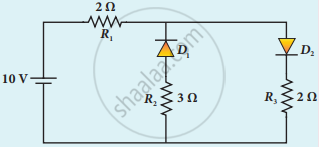
The given circuit has two ideal diodes connected as shown in the figure below. Calculate the current flowing through the resistance R1.

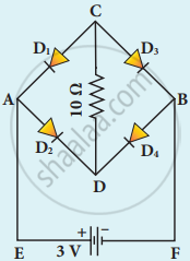
Four silicon diodes and a 10 Ω resistor are connected as shown in the figure below. Each diode has a resistance of 1 Ω. Find the current flows through the 10 Ω resistor.

