Advertisements
Advertisements
Question
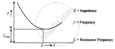
Draw a labelled graph showing a variation of impedance of a series LCR circuit with frequency of the a.c. supply.
Solution

APPEARS IN
RELATED QUESTIONS
A voltage V = V0 sin ωt is applied to a series LCR circuit. Derive the expression for the average power dissipated over a cycle. Under what condition (i) no power is dissipated even though the current flows through the circuit, (ii) maximum power is dissipated in the circuit?
In a series LCR circuit, obtain the condition under which watt-less current flows in the circuit ?
An L-R circuit has L = 1.0 H and R = 20 Ω. It is connected across an emf of 2.0 V at t = 0. Find di/dt at (a) t = 100 ms, (b) t = 200 ms and (c) t = 1.0 s.
Choose the correct answer from given options
The selectivity of a series LCR a.c. circuit is large, when
Choose the correct answer from given options
The phase difference between the current and the voltage in series LCR circuit at resonance is
Keeping the source frequency equal to the resonating frequency of the series LCR circuit, if the three elements, L, C and R are arranged in parallel, show that the total current in the parallel LCR circuit is minimum at this frequency. Obtain the current rms value in each branch of the circuit for the elements and source specified for this frequency.
In an LCR circuit having L = 8 henery. C = 0.5 µF and R = 100 ohm in series, the resonance frequency in radian/sec is
A series LCR circuit containing 5.0 H inductor, 80 µF capacitor and 40 Ω resistor is connected to 230 V variable frequency ac source. The angular frequencies of the source at which power transferred to the circuit is half the power at the resonant angular frequency are likely to be ______.
A series RL circuit with R = 10 Ω and L = `(100/pi)` mH is connected to an ac source of voltage V = 141 sin (100 πt), where V is in volts and t is in seconds. Calculate
- the impedance of the circuit
- phase angle, and
- the voltage drop across the inductor.
