Advertisements
Advertisements
Question
Draw a phasor diagram showing e and i in the case of a purely inductive circuit. A 40-turn square coil of side 0.2 m is placed in a magnetic field of induction 0.05 T with the plane of the coil perpendicular to the direction of the field. If the magnetic induction is uniformly reduced to zero in 5 milliseconds, find the emf induced in the coil.
Solution
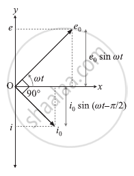
In this case, e = e0 sin ωt and i = i0 sin `(ωt - π/2)`, Where `i_0 = e_0/(ωL)` and L is the inductance of the inductor. This shows that the current i lags behind the emf e by a phase angle of π/2 rad.

Phasor diagram for a purely inductive circuit
Data: N = 40, l = 0.2 m, Bi = 0.5 T, Bf = 0, dt = 5 × 10⁻³ s
A = l2 = (0.2)2 = 0.04 m2
The induced emf,
`e = - (dΦ)/dt`
= `- ((Φ_f - Φ_i))/dt`
= `- (NA(B_f - B_i))/dt`
= `- ((40)(0.04)(0-0.05))/(5 xx 10^-3)`
= `(16 xx 5xx 10^-3)/(5 xx 10^-3)`
= 16 V
