Advertisements
Advertisements
Question
Obtain an expression for average power dissipated in a series LCR circuit.
Solution

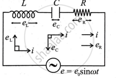
A series LCR circuit consists of a resistor (R), inductor (L), and capacitor (C) connected in series to an AC voltage source. The power dissipated in this circuit depends on the phase difference between the emf and current.
Step 1: Voltage and Current in the Circuit:
The applied AC voltage is:
e = e0 sin ωt
The current in the circuit is:
i = i0 sin(ωt + ϕ)
where:
- e0 = Peak voltage
- i0 = Peak current
- ϕ = Phase angle between voltage and current
- ω = Angular frequency
The instantaneous power is given by:
P = e i
P = e0 sin ωt . i0 sin (ωt + ϕ)
Using the trigonometric identity:
sin A sin B = `1/2[cos(A - B) - cos (A + B)]`
P = `(e_0 i_0)/2[cos (-ϕ) - cos (2ωt + ϕ)]`
Since cos(−ϕ) = cosϕ, taking the average over a complete cycle, the second term (cos(2ωt + ϕ)) averages to zero.
Thus, the average power dissipated is:
`P_(avg) = (e_0 i_0)/2 cos ϕ`
Step 2: Expressing in Terms of RMS Values:
Since RMS values are:
`e_(rms) = (e_0)/sqrt2, i_(rms) = i_0/sqrt2`
`P_(avg) = e_(rms) i_(rms) cos ϕ`
where cosϕ is the power factor of the circuit, given by:
cos ϕ = `R/Z`
where Z is the impedance of the circuit:
Z = `sqrt(R^2 + (X_L - X_C)^2)`
XL = ωL (Inductive reactance)
`X_C = 1/(ωC)` (Capacitive reactance)
Final Expression for Average Power Dissipated
`P_(avg) = e_(rms) i_(rms) cos ϕ`
`P_(avg) = (e_(rms) ^2 R)/Z^2`
Power is dissipated only in the resistor R, as inductors and capacitors store and release energy but do not dissipate it.
If ϕ = 0° (purely resistive circuit), then cosϕ = 1, and maximum power is dissipated.
If ϕ = 90° (purely reactive circuit), then Pavg = 0, meaning no real power dissipation.
Thus, the power dissipation in a series LCR circuit depends on the resistance and power factor of the circuit.
