Advertisements
Advertisements
प्रश्न
Find the equivalent resistance of the network shown in the figure between the points a and b.

उत्तर
The simplified circuit can be drawn as shown below.

Equivalent resistance \[= \frac{1}{\frac{1}{r} + \frac{1}{r} + \frac{1}{r}} = \frac{r}{3}\]
APPEARS IN
संबंधित प्रश्न
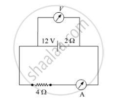
A battery of emf 12 V and internal resistance 2 Ω is connected to a 4 Ω resistor as shown in the figure.
(a) Show that a voltmeter when placed across the cell and across the resistor, in turn, gives the same reading.
(b) To record the voltage and the current in the circuit, why is voltmeter placed in parallel and ammeter in series in the circuit?

Two identical cells of emf 1.5 V each joined in parallel, supply energy to an external circuit consisting of two resistances of 7 Ω each joined in parallel. A very high resistance voltmeter reads the terminal voltage of cells to be 1.4 V. Calculate the internal resistance of each cell.
A cell of emf 'E' and internal resistance 'r' is connected across a variable load resistor R. Draw the plots of the terminal voltage V versus (i) R and (ii) the current I.
It is found that when R = 4 Ω, the current is 1 A and when R is increased to 9 Ω, the current reduces to 0.5 A. Find the values of the emf E and internal resistance r.
A cell of emf 'E' and internal resistance 'r' is connected across a variable resistor 'R'. Plot a graph showing variation of terminal voltage 'V' of the cell versus the current 'I'. Using the plot, show how the emf of the cell and its internal resistance can be determined.
A storage battery of emf 8.0 V and internal resistance 0.5 Ω is being charged by a 120 V dc supply using a series resistor of 15.5 Ω. What is the terminal voltage of the battery during charging? What is the purpose of having a series resistor in the charging circuit?
The earth’s surface has a negative surface charge density of 10−9 C m−2. The potential difference of 400 kV between the top of the atmosphere and the surface results (due to the low conductivity of the lower atmosphere) in a current of only 1800 A over the entire globe. If there were no mechanism of sustaining atmospheric electric field, how much time (roughly) would be required to neutralise the earth’s surface? (This never happens in practice because there is a mechanism to replenish electric charges, namely the continual thunderstorms and lightning in different parts of the globe). (Radius of earth = 6.37 × 10⁶ m.)
Six lead-acid types of secondary cells each of emf 2.0 V and internal resistance 0.015 Ω are joined in series to provide a supply to a resistance of 8.5 Ω. What are the current drawn from the supply and its terminal voltage?
A secondary cell after long use has an emf of 1.9 V and a large internal resistance of 380 Ω. What maximum current can be drawn from the cell? Could the cell drive the starting motor of a car?
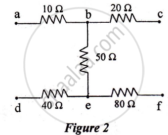
The equivalent resistance between points. a and f of the network shown in Figure 2 is :

a) 24 Ω
b) 110 Ω
c) 140 Ω
d) 200 Ω
Plot a graph showing variation of voltage vs the current drawn from the cell. How can one get information from this plot about the emf of the cell and its internal resistance?
A cell of emf ‘E’ and internal resistance ‘r’ draws a current ‘I’. Write the relation between terminal voltage ‘V’ in terms of E, I and r ?
A cell of emf E and internal resistance r is connected to two external resistance R1 and R2 and a perfect ammeter. The current in the circuit is measured in four different situations:
(i) without any external resistance in the circuit
(ii) with resistance R1 only
(iii) with R1 and R2 in series combination
(iv) with R1 and R2 in parallel combination
The currents measured in the four cases are 0.42 A, 1.05 A, 1.4 A and 4.2 A, but not necessarily in the order. Identify the currents corresponding to the four cases mentioned above.
Two cells of emf E1, E2 and internal resistance r1 and r2 respectively are connected in parallel as shown in the figure.

Deduce the expressions for
(1) the equivalent e.m.f of the combination
(2) the equivalent resistance of the combination, and
(3) the potential difference between the point A and B.
A cell of emf ‘E’ and internal resistance ‘r’ is connected across a variable resistor ‘R’. Plot a graph showing the variation of terminal potential ‘V’ with resistance R. Predict from the graph the condition under which ‘V’ becomes equal to ‘E’.
Apply the first law of thermodynamics to a resistor carrying a current i. Identify which of the quantities ∆Q, ∆U and ∆W are zero, positive and negative.
Two cells of emfs approximately 5 V and 10 V are to be accurately compared using a potentiometer of length 400 cm.
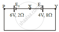
A cell E1 of emf 6 V and internal resistance 2 Ω is connected with another cell E2 of emf 4 V and internal resistance 8 Ω (as shown in the figure). The potential difference across points X and Y is ______.

A block of metal is heated directly by dissipating power in the internal resistance of block. Because of temperature rise, the resistance increases exponentially with time and is given by R(t) = 0.5 e2t, where t is in second. The block is connected across a 110 V source and dissipates 7644 J heat energy over a certain period of time. This period of time is ______ × 10-1 sec (take ln 0.367 = -1).
A cell of emf E is connected across an external resistance R. When current 'I' is drawn from the cell, the potential difference across the electrodes of the cell drops to V. The internal resistance 'r' of the cell is ______.
