Advertisements
Advertisements
प्रश्न
Redraw the circuit of question 1, putting in an ammeter to measure the current through the resistors and a voltmeter to measure the potential difference across the 12 Ω resistors. What would be the readings in the ammeter and the voltmeter?
उत्तर
An ammeter should be connected in the circuit in series with the resistors. To measure the potential difference across the resistor it should be connected in parallel, as shown in the following figure.
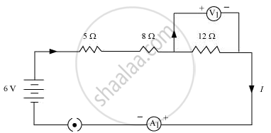
The resistances are connected in series.
Ohm’s law can be used to obtain the readings of ammeter and voltmeter.
According to Ohm’s law,
V = IR,
Where,
Potential difference, V = 6 V
Current flowing through the circuit/resistors = I
Resistance of the circuit, R = 5 + 8 + 12 = 25Ω
I = `V/R`
= `6/25`
= 0.24 A
Potential difference across 12 Ω resistor = V1
Current flowing through the 12 Ω resistor, I = 0.24 A
Therefore, using Ohm’s law, we obtain
V1 = IR
= 0.24 × 12
= 2.88 V
Therefore, the reading of the ammeter will be 0.24 A.
The reading of the voltmeter will be 2.88 V.
संबंधित प्रश्न
What do the following symbols mean in circuit diagrams?

What do the following symbols mean in circuit diagrams?

Draw circuit symbols for
an open switch
Draw a circuit diagram to show how 3 bulbs can be lit from a battery so that 2 bulbs are controlled by the same switch the third bulb has its own switch.
Explain with the help of a labelled circuit diagram how you will find the resistance of a combination of three resistors, or resistance R1, R2 and R3, joined in parallel. Also mention how you will connect the ammeter and the voltmeter in the circuit when measuring the current in the circuit and the potential difference across one of the three resistors of the combination.
Two tungsten bulbs of power 50 W and 60 W work on 220 V potential difference. If they are connected in parallel, how much current will flow in the main conductor?
Resistances R1, R2, R3 and R4 are connected as shown in the figure. S1 and S2 are two keys. Discuss the current flowing in the circuit in the following cases.
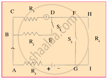
- Both S1 and S2 are closed.
- Both S1 and S2 are open.
- S1 is closed but S2 is open.
What do you understand by the closed electric circuit
The unit of electrical power is _______.
Increasing the current passing through the wire decreases the magnetic field intensity.
What is the use of earthing wire?
A device that is used to break an electric circuit is called ______.
What are the types of electric circuits?
Choose the statement which is not correct in the case of an electric fuse.
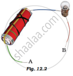
In the following arrangement shown in Fig. 12.2, the bulb will not glow if the ends A and B are connected with
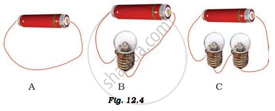
In which of the following circuits A, B, and C gave in Fig. 12.4, the cell will be used up very rapidly?
Overloading of electric circuits can lead to short-circuiting.
Assertion: People struck by lightning receive a severe electrical shock.
Reason: Lightning carries very high voltage.
Set up the circuit shown in Figure again. Move the key to ‘ON’ position and watch carefully in which direction the compass needle gets deflected. Switch ‘OFF’ the current. Now keeping rest of the circuit intact, reverse the connections at the terminal of the cell. Again switch ‘on’ the current. Note the direction in which the needle gets deflected. Think of an explanation.
