Advertisements
Advertisements
प्रश्न
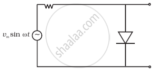
The output of the given circuit in figure is given below.

विकल्प
would be zero at all times.
would be like a half wave rectifier with positive cycles in output.
would be like a half wave rectifier with negative cycles in output.
would be like that of a full wave rectifier.
उत्तर
Would be like a half-wave rectifier with negative cycles in output.
Explanation:

(i) During the positive half cycle,
Diode → forward biased
Output signal → obtained
(ii) During the negative half cycle,
Diode → reverse biased
Output signal → not obtained
(iii) Output voltage is obtained across the load resistance R1. It is not constant but pulsating (mixture of ac and dc) in nature.
(iv) Average output in one cycle
(v) r.m.s output: `I_(rms) = I_0/2, V_(rms) = V_0/2`
When the diode is forward-biased during the positive half cycle of input AC voltage, the resistance of the p-n junction is low. The current in the circuit is maximum. In this situation, a maximum potential difference will appear across resistance connected in a series of circuits. This result in zero output voltage across the p-n junction.
And when the diode is reverse biased during the negative half cycle of AC voltage, the p-n junction is reverse biased. The resistance of the p-n junction becomes high which will be more than resistance in series. That is why there will be the voltage across p-n junction with a negative cycle in output,
APPEARS IN
संबंधित प्रश्न
Draw the circuit diagram of a full wave rectifier. Explain its working showing its input and output waveforms.
Briefly explain how the output voltage/current is unidirectional.
In half-wave rectification, what is the output frequency if the input frequency is 50 Hz. What is the output frequency of a full-wave rectifier for the same input frequency.
When the diode shows saturated current, dynamic place resistance is _____________ .
Fill in the blank.
The ability of a junction diode to __________ an alternating voltage is based on the fact that it allows current to pass only when it is forward biased.
Draw the circuit diagram of a full wave rectifier.
Explain with a proper diagram how an ac signal can be converted into dc (pulsating) signal with output frequency as double than the input frequency using pn junction diode. Give its input and output waveforms.
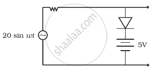
Assuming the ideal diode, draw the output waveform for the circuit given in figure. Explain the waveform.

With the help of a circuit diagram, explain briefly how a p-n junction diode works as a half-wave rectifier.
Draw a labelled circuit diagram of a full wave rectifier. Show graphically how the output voltage varies with time.
