Advertisements
Advertisements
प्रश्न
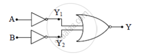
The outputs of two NOT gates are fed to a NOR gate. Draw the logic circuit of the combination of gates. Write its truth table. Identify the gate equivalent to this circuit.
उत्तर

`"Y"_1 = bar"A"`
`"Y"_2 = bar"B"`
`"Y" = overline("Y"_1+"Y"_2) = overline(bar"A"+bar"B") = underset(A)(=) underset(B)(=) = "A.B"`
he equivalent gate is AND gate
Truth table
| A | B | Y1 | Y2 | Y |
| 0 | 0 | 1 | 1 | 0 |
| 0 | 1 | 1 | 0 | 0 |
| 1 | 0 | 0 | 1 | 0 |
| 1 | 1 | 0 | 0 | 1 |
APPEARS IN
संबंधित प्रश्न
Which logic gate corresponds to the truth table given below?
|
A |
B |
Y |
|
0 |
0 |
I |
|
0 |
1 |
0 |
|
1 |
0 |
0 |
|
1 |
1 |
0 |
The output of NOR gate is high, when _______.
The arrangement given below represents a logic gate :

Copy the following truth table in your answer booklet and complete it showing outputs at C
and D.
| A | B | C | D |
| 0 | 0 | ||
| 1 | 0 | ||
| 0 | 1 | ||
| 1 | 0 |
Let \[X = A \overline{ BC} + B\overline{ CA} + C\overline{AB } .\] Evaluate X for A = B = C = 1.
(i) Write the truth tables of the logic gates marked P and Q in the given circuit.
(ii) Write the truth table for the circuit.

Why are NOR gates considered as universal gates?
The truth table for the following logic circuit is:

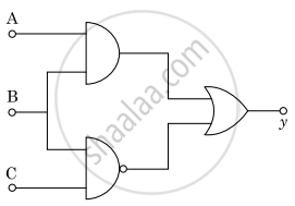
For the given circuit, the input digital signals are applied at terminals A, B, and C. What would be the output at terminal y?


How would you set up a circuit to obtain NOT gate using a transistor?
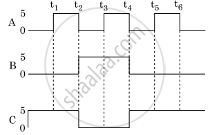
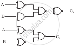
Draw the output signals C1 and C2 in the given combination of gates (Figure).


