Advertisements
Advertisements
प्रश्न
Explain, with the help of a circuit diagram, the principle and working of a Zener diode as voltage regular.
Explain the working of Zener diode as a voltage regulator.
उत्तर
Principle
A properly doped p–n junction that is supposed to work in a breakdown region is called a Zener diode. Such a junction when reverse biased shows a sudden increase in current to a high value at a certain voltage known as the breakdown voltage or the Zener voltage.

Working:
A Zener diode can be used as a voltage regulator to provide a constant alue of voltage from a source whose value fluctuates over a wide range.
Given below is a circuit diagram. A Zener diode is connected across the fluctuating voltage source through a resistance R. A constant voltage supply is maintained across the load resistance RL.
When the input voltage increases, the resistance of the Zener diode decreases, and hence the current through the diode increases. Thus, a large voltage drop is seen across the resistance R and the output voltage across RL remains at a constant value. When the input voltage decreases, the resistance of the Zener diode increases and hence the current through the diode decreases. Only a small voltage drop takes place now across the resistance R, and the output voltage at RL remains constant. Thus, we get a constant voltage in spite of the fluctuating input voltage. In this way, a Zener diode acts as a voltage regulator.

Notes
Students should refer to the answer according to their question and preferred marks.
APPEARS IN
संबंधित प्रश्न
Describe, with the help of a circuit diagram, the working of Zener diode as a voltage regulator.
What is Zener diode?
Draw the circuit diagram of zener diode as a voltage regulator and briefly explains its working ?
Name the device which is used as a voltage regulator. Draw the necessary circuit diagram and explain its working?
Draw the I − V characteristics of zener diode and explain briefly how reverse current suddenly increase at the breakdown voltage.
Describe briefly with the help of a circuit diagram how a zener diode works to obtain a constant dc voltage from the unregulated dc output of a rectifier ?
Draw labelled graphs showing the input and output voltages.
In the circuit shown in the figure, the potential barrier for Ge diode is 0.3 V and for Si diode it is 0.7 V. What is the voltage VA?

Electronic motors operating at low voltages tend to burn out because
For a chosen non-zero value of voltage, there can be more than one values of current in
Consider the following statements (A) and (B) and identify the correct answer.
(A) A Zener diode is connected in reverse bias when used as a voltage regulator.
(B) The potential barrier of the p-n junction lies between 0.1 V to 0.3 V.
Consider the following statements (A) and (B) and identify the correct answer.
- A zener diode is connected in reverse bias, when used as a voltage regulator.
- The potential barrier of p-n junction lies between 0.1 V to 0.3 V.
What happens during regulation action of a Zener diode?
- The current in and voltage across the Zenor remains fixed.
- The current through the series Resistance (Rs) changes.
- The Zener resistance is constant.
- The resistance offered by the Zener changes.
For the circuit shown below, calculate the value of Iz ______.

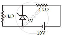
In connection with the circuit drawn below, the value of current flowing through 2 kΩ resistor is ______ × 10-4 A.

The reverse breakdown voltage of a Zener diode is 5.6 V in the given circuit.

The current Iz through the Zener is ______.
A Zener diode is to be used as a voltage regulator. Identify the correct setup.
