Advertisements
Advertisements
प्रश्न
State the working principle of a potentiometer. With the help of the circuit diagram, explain how a potentiometer is used to compare the emf's of two primary cells. Obtain the required expression used for comparing the emfs.
उत्तर
Working principle of Potentiometer:
When a constant current is passed through a wire of uniform area of cross-section, the potential drop across any portion of the wire is directly proportional to the length of that portion.
Applications of Potentiometer for comparing emf of two cells:
The following Figure shows an application of the potentiometer to compare the emf of two cells of emf E1 and E2

E1, E2 is the emf of the two cells.
1, 2, 3 forms a two-way key.
When 1 and 3 are connected, E1 is connected to the galvanometer (G).
Jokey is moved to N1, which is at a distance l1 from A, to find the balancing length.
Applying loop rule to AN1G31A,
Φ l1 + 0 − E1 = 0 ..(1)
Where Φ is the potential drop per unit length
Similarly, for E2 balanced against l2 (AN2),
Φ l2 + 0 −E2 = 0 ..(2)
From equations (1) and (2),
`E_1/E_2 = I_1/I_2` .....(3)
Thus we can compare the emfs of any two sources. Generally, one of the cells is chosen as a standard cell whose emf is known to a high degree of accuracy.
APPEARS IN
संबंधित प्रश्न
Accuracy of potentiometer can be easily increased by ______.
A potentiometer wire of length 1 m has a resistance of 5 Ω. It is connected to a 8 V battery in series with a resistance of 15 Ω. Determine the emf of the primary cell which gives a balance point at 60 cm.
Draw a labelled circuit diagram of a potentiometer to compare emfs of two cells. Write the working formula (Derivation not required).
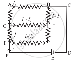
Find the equivalent resistance between the terminals of A and B in the network shown in the figure below given that the resistance of each resistor is 10 ohm.

What will be the effect on the position of zero deflection if only the current flowing through the potentiometer wire is decreased?
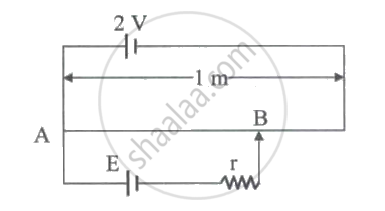
In the given figure, battery E is balanced on 55 cm length of potentiometer wire but when a resistance of 10 `Omega` is connected in parallel with the battery, then it balances on 50 cm length of the potentiometer wire. The internal resistance r of the battery is ____________.

A potentiometer is used to measure the potential difference between A and B, the null point is obtained at 0.9 m. Now the potential difference between A and C is measured, the null point is obtained at 0.3 m. The ratio `E_2/E_1` is (E1 > E2) ______

AB is a wire of potentiometer with the increase in value of resistance R, the shift in the balance point J will be:

What will a voltmeter of resistance 200 Ω read when connected across a cell of emf 2 V and internal resistance 2 Ω?
