Advertisements
Advertisements
प्रश्न
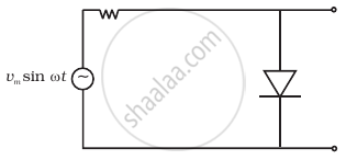
With the help of a circuit diagram, explain briefly how a p-n junction diode works as a half-wave rectifier.
उत्तर
Half-Wave rectifier: The rectifier that converts only one-half of ac into dc is called a half-wave rectifier.
Circuit diagram:

Working:
The primary coil of the transformer receives the ac input signal that needs to be rectified. A load resistance RL and a junction diode are connected in series with the secondary coil.
Point A of the secondary coil is positive and point B is at zero potential for positive ac half cycles. The junction diode is forward biassed because A is connected to the junction diode's p-region. The junction diode conducts as a result. RL is crossed to obtain the output voltage, which fluctuates in accordance with the input half cycle.
Point A is negative and point B is at zero potential for negative half cycles of ac. Since it is reverse biassed, the junction diode. As a result, there is no output across load resistance since the junction diode does not conduct.
The output variation corresponding to the input is shown below:

APPEARS IN
संबंधित प्रश्न
Briefly explain how the output voltage/current is unidirectional.
Draw the circuit diagram of a half wave rectifier and explain its working.
In half-wave rectification, what is the output frequency if the input frequency is 50 Hz. What is the output frequency of a full-wave rectifier for the same input frequency.
Fill in the blank.
The ability of a junction diode to __________ an alternating voltage is based on the fact that it allows current to pass only when it is forward biased.
A 220 V A.C. supply is connected between points A and B (figure). What will be the potential difference V across the capacitor?

The output of the given circuit in figure is given below.

To reduce the ripples in a rectifier circuit with capacitor filter ______.
- RL should be increased.
- input frequency should be decreased.
- input frequency should be increased.
- capacitors with high capacitance should be used.
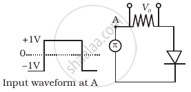
Draw the output waveform across the resistor (Figure).
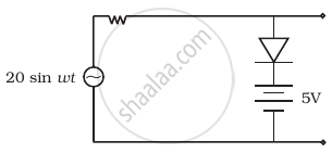
Assuming the ideal diode, draw the output waveform for the circuit given in figure. Explain the waveform.

Give two differences between a half-wave rectifier and a full-wave rectifier.
