Advertisements
Advertisements
Question
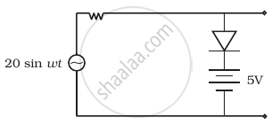
Assuming the ideal diode, draw the output waveform for the circuit given in figure. Explain the waveform.

Solution
An ideal diode is a diode which it has very large resistance in reverse biased and very, low resistance in forward biased. So, it acts like a perfect conductor when voltage is applied forward-biased and like a perfect insulator when voltage is applied reverse-biased.
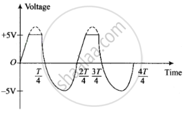
In reverse biased when the input voltage is equal to or less than 5 V diode, then it will offer high resistance in comparison to resistance (R) in series. Now, the diode appears in an open circuit. The input waveform is then passed to the output terminals. The result with sin wave input is to dip off all positive going portions above 5 V.
If the input voltage is greater than +5 V, the diode is in conducting state, then it will be conducting as if forward biased offering low resistance in comparison to R. But there will be no voltage in output beyond 5 V as the voltage beyond +5 V will appear across R.
When the input voltage is negative, there will be opposition to 5 V battery in p-n junction input voltage becomes more than –5 V, the diode will be reverse biased. It will offer high resistance in comparison to resistance R in series. Now junction diode appears in an open circuit. The input waveform is then passed on to the output terminals.
The output waveform will be like this (as shown below).

APPEARS IN
RELATED QUESTIONS
Draw the circuit diagram of a full wave rectifier. Explain its working showing its input and output waveforms.
In half-wave rectification, what is the output frequency if the input frequency is 50 Hz. What is the output frequency of a full-wave rectifier for the same input frequency.
Fill in the blank.
The ability of a junction diode to __________ an alternating voltage is based on the fact that it allows current to pass only when it is forward biased.
Draw the circuit diagram of a full wave rectifier.
The device which uses centre-tapped secondary of the transformer is
To reduce the ripples in a rectifier circuit with capacitor filter ______.
- RL should be increased.
- input frequency should be decreased.
- input frequency should be increased.
- capacitors with high capacitance should be used.
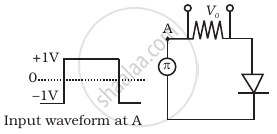
Draw the output waveform across the resistor (Figure).
With the help of a circuit diagram, explain briefly how a p-n junction diode works as a half-wave rectifier.
Give two differences between a half-wave rectifier and a full-wave rectifier.
With the help of a circuit diagram, explain how a full wave rectifier gives output rectified voltage corresponding to both halves of the input ac voltage.
