Advertisements
Advertisements
Question
Draw a neat diagram of a full-wave rectifier and explain it’s working.
Solution
A device or a circuit which rectifies both halves of each cycle of an alternating voltage is called a full-wave rectifier.
Electric circuit: The alternating voltage to be rectified is applied across the primary coil (P1P2) of a transformer with a center-tapped secondary coil (S1S2). The terminals S1 and S2 of the secondary are connected to the two p-regions of two junction diodes D1 and D2, respectively. The center-tap Tis connected to the ground. The load resistance RL is connected across the common n-regions and the ground.

Full-wave rectifier circuit
P1P2, S1S2 - Primary and secondary transformer,
T - Centre-tap on secondary,
D1, D2 - Junction diodes,
RL - Load resistance,
IL - Load current,
Vi - AC input voltage,
Vo - DC output voltage
Working: During the one-half cycle of the input, terminal S1 of the secondary is positive while S2 is negative with respect to the ground (the centre-tap T). During this half cycle, diode D1 is forward biased and conducts, while diode D2 is reverse biased and does not conduct. The direction of current IL through RL is in the sense shown.

Voltage waveforms for a full-wave rectifier
(a) input (b) output
During the next half-cycle of the input voltage, S2 becomes positive while S, is negative with respect to T. Diode D2 now conducts sending a current IL through RL in the same sense as before. D1 now does not conduct. Thus, the current through RL flows in the same direction, i.e., it is unidirectional, for both halves or the full wave of the input. This is called full-wave rectification. The output voltage has a fixed polarity but varies periodically with the time between zero and a maximum value. The above figure shows the input and output voltage waveforms. The pulsating de output voltage of a full-wave rectifier has twice the frequency of the input.
APPEARS IN
RELATED QUESTIONS
Draw the circuit diagram of a half-wave rectifier. Explain its working. What is the frequency of ripple in its output?
Draw the circuit diagram of a half-wave rectifier. Hence explain its working.
Draw a neat labelled circuit diagram of a full-wave rectifier using a semiconductor diode.
State the advantages of a full-wave rectifier.
The electrical resistance of depletion layer is large because ____________.
A junction diode of internal resistance 20 Ω is used for half-wave rectification. If the applied voltage has a peak value of 50 V and load resistance is 800 Ω, then d.c. value of current is ____________.
The maximum efficiency of full-wave rectifier is ____________.
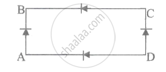
In figure, the input is across the terminals A and C and the output is across B and D. Then, the output is ____________.
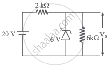
What is the value of output voltage V0 in the given circuit?
What is a rectifier?
If a centre tap transformer is used with 2 diodes for full-wave rectification, then output voltage of rectifier w.r.t. each diode is ______.
With a neat circuit diagram, explain the working of a full-wave rectifier. Draw the input and output voltage waveforms.
What is the ripple factor?
If the frequency of the input voltage 50 Hz is applied to a full wave rectifier, what will be the output frequency?
A photodiode is used in ______.
Write a short note on Full wave rectifier.
