Advertisements
Advertisements
Question
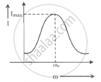
For a series LCR circuit, I vs ω curve is shown:

- To the left of ωr, the circuit is mainly capacitive.
- To the left of ωr, the circuit is mainly inductive.
- At ωr, impedance of the circuit is equal to the resistance of the circuit.
- At ωr, impedance of the circuit is 0.
Options
(a) and (d) only
(b) and (d) only
(a) and (c) only
(b) and (c) only
Solution
At ωr, impedance of the circuit is equal to the resistance of the circuit.
Explanation:
At resonance XL = XC and impedance of circuit is minimum and is equal to R and current is maximum.
At resonance, ω0 = `1/sqrt("LC")`
⇒ When current exceeds voltage and the circuit is capacitive, the potential drop across the capacitor exceeds that across the inductor.
⇒ The circuit becomes inductive if the potential drop across the inductor is greater than the potential drop across the capacitor.
Thus, i0XL > i0XC Circuit is inductive
XL > XC
ωL > `1/(ω"C")`
ω2 > `1/sqrt("LC")`
ω > `sqrt(1/sqrt("LC"))`
ω > ωR
i0XC > i0XL Circuit is inductive
XC > XL
1/ωC > ωL
ω < `1/sqrt("LC")`
ω < `sqrt(1/sqrt("LC"))`
ω < ωR
