Advertisements
Advertisements
Question
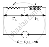
The potential difference across the resistor is 160 V and that across the inductor is 120 V. Find the effective value of the applied voltage. If the effective current in the circuit is 1⋅0 A, calculate the total impedance of the circuit.
Solution
We have,

VR = 160 V
VL = 120 V
Vnet = 200 V
Inet = 1 A
APPEARS IN
RELATED QUESTIONS
Draw a graph to show variation of capacitive-reactance with frequency in an a.c. circuit.
Three capacitors of capacities 8 μF, 8 μF and 4 μF are connected in a series and potential difference of 120 volt is maintained across the combination. Calculate the charge on capacitor of capacity 4 μF.
A light bulb is rated at 120 W for a 220 V a.c. supply. Calculate the resistance of the bulb.
A light bulb is rated 100 W for 220 V ac supply of 50 Hz. Calculate
(i) The resistance of the bulb;
(ii) The rms current through the bulb.
What is the reactance of a capacitor connected to a constant DC source?
When the frequency of the AC source in an LCR circuit equals the resonant frequency, the reactance of the circuit is zero. Does it mean that there is no current through the inductor or the capacitor?
The reactance of a circuit is zero. It is possible that the circuit contains
(a) an inductor and a capacitor
(b) an inductor but no capacitor
(c) a capacitor but no inductor
(d) neither an inductor nor a capacitor
(i) An alternating emf of 200 V, 50 Hz is applied to an L-R ciruit, having a resistance R of 10 Ω and an inductance L of 0.05H connected in series. Calculate :
(1) Impedance
(2) Current flowing in the circuit
(ii) Draw a labelled graph showing the variation of inductive reactance (
A series combination of an inductor (L), capacitor (C) and a resistor (R) is connected across an ac source of emf of peak value E0, and angular frequency (ω). Plot a graph to show variation of impedance of the circuit with angular frequency (ω).
In a pure capacitive circuit if the frequency of ac source is doubled, then its capacitive reactance will be ______.
