Advertisements
Advertisements
Question
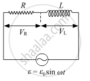
An ac circuit as shown in the figure has an inductor of inductance L and a resistor of resistance R connected in series. Using the phasor diagram, explain why the voltage in the circuit will lead the current in phase.

Solution
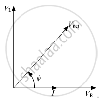
Phasor Diagram of the above circuit will be:

Net voltage `= sqrt("V"_2^2 + "V"_"R"^2)` will ahead of current by Φ
`tan phi = "V"_2/("V"_"R")`
APPEARS IN
RELATED QUESTIONS
The power factor of an a.c. circuit is 0.5. What is the phase difference between voltage and current in this circuit ?
For a given a.c., i = im sin ωt, show that the average power dissipated in a resistor R over a complete cycle is `1/2I_m^2` R .
Transformers are used ______.
In an AC series circuit, the instantaneous currt is zero when the instantaneous voltage is maximum. Connected to the source may be a
(a) pure inductor
(b) pure capacitor
(c) pure resistor
(d) combination of an inductor and a capacitor
An electric bulb is designed to consume 55 W when operated at 110 volts. It is connected to a 220 V, 50 Hz line through a choke coil in series. What should be the inductance of the coil for which the bulb gets correct voltage?
Consider the situation of the previous problem. Find the average electric field energy stored in the capacitor and the average magnetic field energy stored in the coil.
In which of the following circuits the maximum power dissipation is observed?
The power factor in a circuit connected to an A.C. The value of power factor is ______.
Which of the following quantities remains constant in a step-down Transformer?
The power factor of an a.c circuit having resistance R and inductance L Connected in series to an a.c source of angular frequency co is.
