Topics
Operating System
- Introduction to Operating System (OS)
- Idea of an Operating System
- Windows NT
- LINUX
- File Systems and Its types
- File Operations
- Access Methods and its types
- Allocation Methods
- Concepts Related to Process Management
- Concepts related to memory management
- Basics of Graphical User Interface (GUI)
- Access and Security Aspects of O.S.
Data Structures
C++ Programming
- Introduction to C++ Programming
- Idea Behind Object-Orientated Programming
- Object-orientated programming approach
- Object-Oriented Terms and Concepts
- Classes and Objects
- Constructors and Destructors
- Functions in C + +
- Arrays in C++
- Pointers in C++
- References in C++
- Strings in C++
- Inheritance
- Virtual functions and polymorphism
- Friends in C++
- Operator overloading and type conversions
- Files and Stream
HyperTex Markup Language (HTML)
Stack and Queue
Many times, we want to restrict insertion and deletion operations, so that they can take place only at the beginning or at the end of list, not in the middle. The data structures Stack and Queue are useful in such situations.
A Stack is a data structure in which items may be added or removed only at one end. The common examples of a stack are stack of dishes, a stack of books etc. "Push" is the term used to insert an element into a stack. "Pop" is the term used to delete an element from a stack. A stack is also called as last-in-first-out (LIFO) list.
A queue is a linear list in which items may be added only at one end and items may be removed only at other end. The common example of queue is the queue waiting for a bus at bus stop. The queue is also called as first-in-first-out (FIFO) list.
Stack, I/0 and Machine Control Instructions
PUSH rp & PUSH PSW (Push processor status word)
PUSH instruction is used to push anything into the stack area. It i used by programmers very often.
PUSH rp: [(SP) - 1] <- (rh)
[(SP) - 2] <- (rl)
(SP) <- (SP) - 2
In this one-byte instruction, the high-order register of the register pair rp is stored at the memory location SP-1, and the low-order register at SP-2. The stack pointer (SP) is then decremented by two. No flag is affected
PUSH PSW: [(SP) - 1] <- (A)
[(SP) - 2]0 <- (cy), [(SP) - 2]1 <- x.
[(SP) - 2]2<- (P), [(SP) - 2]3<- x
[(SP) - 2] 4<- (AC), [(SP) - 2]5<- x
[(SP) - 2] 6 <- (z), [(SP) - 2)]7 <- (S)
(SP) <- (SP) - 2 x : undefined
In this one-byte instruction, the content of register A is stored at the memory location SP-1. The condition flags are combined into a processor status word and stored at SP-2. The stack pointer (SP) is then decremented by two. No flag are affected.
POP rp (POP) & POP PSW (POP Processor status word)
POP is used to extract content from stack area. It is just the opposite of PUSH instruction which is used to put content in the stack area.
POP rp: (rl) <- [(SP)]
(rh) <- [(SP) + 1]
(SP) <- (SP) + 2
In this one-byte instruction, the memory content at the address specified by SP is moved to the low-order register of rp, and the memory content at SP+1 is moved to the high-order register of rp. The stack pointer (SP) is incremented by two. The register pair rp may not be specified. Addressing Mode: Register Indirect
POP PSW: (CY) <- [(SP)]0
(P) <- [(SP)]2 (AC) < [(SP)]4
(Z) <- [(SP)]6 (S) <- [(SP)]7
(A) <- [(SP)+ 1] (SP) <- (SP) + 2
The content of memory location whose address is specified by the content of register SP is used to restore the condition flags. The content of memory location whose address is one more than SP is moved to register A (Accumulator). The contents of SP are incremented by 2. This is one byte instruction. Addressing Mode: Register indirect Addressing
XTHL (Exchange stack top with H and L) & SPHL (Move HL to SP)
XTHL: (L) <- [(SP)]
(H) <- [(SP) + 1]
In this one-byte instruction, the L register content is exchanged with the memory content at the address specified by SP. The H register content is exchanged with the memory content at SP+1. Addressing Mode: Register indirect addressing
SPHL: (SP) <- (H) (L)
The contents of registers Hand L (16 bits) are moved to register SP. This is one byte instruction. This instruction can be used for initializing the stack pointer. Addressing Mode: Register addressing
IN port (Input) & OUT port (Output)
IN port: (A) <- (data),
The data placed on the eight bit bidirectional data bus by the specified port is moved to register A. This is two byte instruction. In the second byte, data is given. Addressing Mode: Direct Addressing.
OUT port: (Output) <- (A) ,
This is two byte instruction. The content of register A is placed on the eight bit bidirectional data bus for transmission to the specified port. Addressing Mode: Direct Addressing.
In both the instructions no flag is affected.
EI (Enable Interrupt) & DI (Disable Interrupts)
EI: The interrupt will be recognized after the execution of this step; even if any interrupt is generated during the execution of EI then it will be ignored. This is one byte instruction.
DI: The interrupt system is disabled immediately following the execution of DI instruction. Interrupts are not recognized during the DI instruction. This is one byte instruction.
In execution of both the instructions no flags are affected. Both use implied addressing mode.
HLT (Halt) & NOP (NO OP)
HLT (Halt): The processor is stopped. The registers and flags are unaffected. This is one byte instruction. This is used to stop MPU. It is waiting for a peripheral device to finish its task.
NOP (NO OP): No operation is performed. The register and flags are unaffected. This is one byte instruction. This instruction is useful as a time delay in a timing loop.
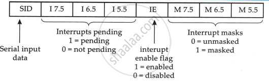
RIM (Read Interrupt Masks)
The RIM instruction loads data into the accumulator relating to interrupts and the serial input. This data contains the following information:
- Current interrupt mask status for the RST5.5, 6.5 and 7.5 hardware interrupts (1 = Mask disabled)
- Current interrupt enable flag status (1 =interrupts enabled) except immediately following a TRAP interrupt.
- Hardware interrupts pending (i.e. signal received but not yet serviced), on the RST 5.5, 6.5 and 7.5 Lines.
- Serial input data.
Immediately following a TRAP interrupt, the RIM instruction must be executed as a part of service routine if you need to retrieve current interrupt status later. Accumulator contents after RIM are shown below:
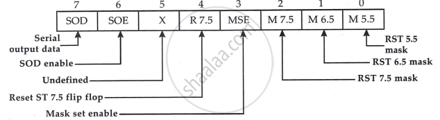
SIM (Set interrupt masks)
The SIM (Set Interrupt Mask) instruction in the Intel 8085 microprocessor is a multi-functional command that uses the contents of the accumulator to perform various control operations. The primary functions of the SIM instruction are to program the interrupt mask for the RST 5.5, 6.5, and 7.5 hardware interrupts, reset the edge-triggered RST 7.5 input latch, and load the SOD (Serial Output Data) output latch. To program the interrupt masks, bit 3 of the accumulator must be set to 1, and bits 0, 1, and 2 should be set to 1 to disable the respective interrupts. If bit 3 is 0 during execution, the interrupt mask register remains unchanged. The RST 7.5 latch, set by a rising edge on the input pin, can be reset if bit 4 of the accumulator is 1 during the SIM instruction. This latch can also be cleared by the RESETIN signal or an internal processor acknowledgment. Additionally, if bit 6 of the accumulator is 1, the state of bit 7 is loaded into the SOD latch for interfacing with external devices. The SOD latch remains unaffected if bit 6 is 0 and is reset by the RESETIN signal. Overall, the SIM instruction offers versatile control over hardware interrupts and external device communication, enhancing the microprocessor's interrupt handling and interfacing capabilities.