Advertisements
Advertisements
प्रश्न
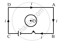
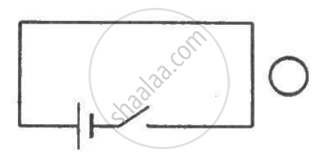
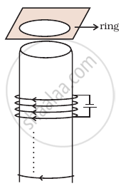
Consider the situation shown in figure. If the closed loop is completely enclosed in the circuit containing the switch, the closed loop will show _______________ .
विकल्प
an anticlockwise current-pulse
a clockwise current-pulse
an anticlockwise current-pulse and then a clockwise current-pulse
a clockwise current-pulse and then an anticlockwise current-pulse
उत्तर
an anticlockwise current-pulse and then a clockwise current-pulse
According to Lenz's law, the induced current in the loop will be such that it opposes the increase in the magnetic field due to current flow in the circuit. Therefore, the direction of the induced current when the switch is closed is anti-clockwise.
Similarly, when the switch is open, there is a sudden fall in the current, leading to decrease in the magnetic field at the centre of the loop. According to Lenz's law, the induced current in the loop is such that it opposes the decrease in the magnetic field. Therefore, the direction of the induced current when the switch is open is clockwise.
APPEARS IN
संबंधित प्रश्न
What is the direction of induced currents in metal rings 1 and 2 when current I in the wire is increasing steadily?
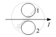
Predict the directions of induced currents in metal rings 1 and 2 lying in the same plane where current I in the wire is increasing steadily.
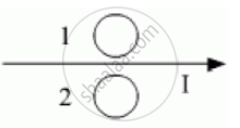
Predict the direction of induced current in metal rings 1 and 2 when current I in the wire is steadily decreasing?
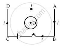
Consider the situation shown in figure. If the switch is closed and after some time it is opened again, the closed loop will show ____________ .
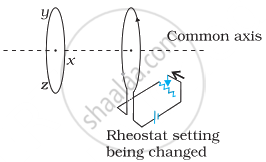
Two circular loops of equal radii are placed coaxially at some separation. The first is cut and a battery is inserted in between to drive a current in it. The current changes slightly because of the variation in resistance with temperature. During this period, the two loops _______________ .
Which of the following statements is not correct?
There are two coils A and B as shown in figure. A current starts flowing in B as shown, when A is moved towards B and stops when A stops moving. The current in A is counterclockwise. B is kept stationary when A moves. We can infer that ______.

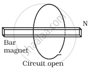
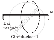
Consider a magnet surrounded by a wire with an on/off switch S (Figure). If the switch is thrown from the off position (open circuit) to the on position (closed circuit), will a current flow in the circuit? Explain.
A wire in the form of a tightly wound solenoid is connected to a DC source, and carries a current. If the coil is stretched so that there are gaps between successive elements of the spiral coil, will the current increase or decrease? Explain.
Consider a metal ring kept on top of a fixed solenoid (say on a carboard) (Figure). The centre of the ring coincides with the axis of the solenoid. If the current is suddenly switched on, the metal ring jumps up. Explain
A metallic ring of mass m and radius `l` (ring being horizontal) is falling under gravity in a region having a magnetic field. If z is the vertical direction, the z-component of magnetic field is Bz = Bo (1 + λz). If R is the resistance of the ring and if the ring falls with a velocity v, find the energy lost in the resistance. If the ring has reached a constant velocity, use the conservation of energy to determine v in terms of m, B, λ and acceleration due to gravity g.
A long solenoid ‘S’ has ‘n’ turns per meter, with diameter ‘a’. At the centre of this coil we place a smaller coil of ‘N’ turns and diameter ‘b’ (where b < a). If the current in the solenoid increases linearly, with time, what is the induced emf appearing in the smaller coil. Plot graph showing nature of variation in emf, if current varies as a function of mt2 + C.
A coil is suspended in a uniform magnetic field, with the plane of the coil parallel to the magnetic lines of force. When a current is passed through the coil it starts oscillating: It is very difficult to stop. But if an aluminium plate is placed near to the coil, it stops. This is due to:
Predict the direction of induced current in the situation described by the following figure.
Predict the direction of induced current in the situation described by the following figure.