Advertisements
Advertisements
प्रश्न
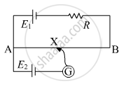
In the circuit diagram given below, AB is a uniform wire of resistance 15 Ω and length 1 m. It is connected to a cell E1 of emf 2V and negligible internal resistance and a resistance R. The balance point with another cell E2 of emf 75 mV is found at 30 cm from end A. Calculate the value of R.

उत्तर
As per the figure,
Total current through the wire AB is given by
\[I = \frac{E}{R + r}\]
\[ = \frac{2}{R + 15}\]
The potential gradient of the wire is given by
\[= I \times \frac{15}{100}\]
\[ = \frac{2}{R + 15} \times \frac{15}{100}\]
As, the balance point with cell E2 of emf 75 mV is found at 30 cm from end A
\[\frac{2}{R + 15} \times 0 . 15 \times 30 = 75 \times {10}^{- 3} \]
\[\left( \frac{2}{75 \times {10}^{- 3}} \times 0 . 15 \times 30 \right) - 15 = R\]
\[R = 105 \Omega\]
APPEARS IN
संबंधित प्रश्न
Define 1 volt PD.
Distinguish between Conductors and Insulators.
A metal rod of square cross-sectional area A having length l has current I flowing through it when a potential difference of V volt is applied across its ends (figure I). Now the rod is cut parallel to its length into two identical pieces and joined as shown in figure II. What potential difference must be maintained across the length of 2l. so that the current in the rod is still I?

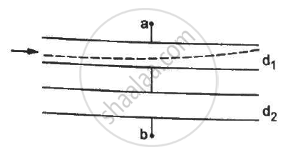
Both the capacitors shown in figure are made of square plates of edge a. The separations between the plates of the capacitors are d1 and d2 as shown in the figure. A potential difference V is applied between the points a and b. An electron is projected between the plates of the upper capacitor along the central line. With what minimum speed should the electron be projected so that it does not collide with any plate? Consider only the electric forces.

A charge of `+2.0 xx 10^-8 C` is placed on the positive plate and a charge of `-1.0 xx 10^-8 C` on the negative plate of a parallel-plate capacitor of capacitance `1.2 xx 10^-3 "uF"` . Calculate the potential difference developed between the plates.
A charge of 20 µC is placed on the positive plate of an isolated parallel-plate capacitor of capacitance 10 µF. Calculate the potential difference developed between the plates.
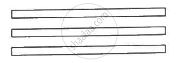
The capacitance between the adjacent plates shown in figure is 50 nF. A charge of 1⋅0 µC is placed on the middle plate. (a) What will be the charge on the outer surface of the upper plate? (b) Find the potential difference developed between the upper and the middle plates.

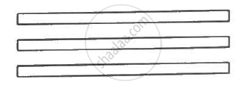
The capacitance between the adjacent plates shown in the figure is 50 nF. A charge of 1.0µC is placed on the middle plate. If 1.0 µC is placed on the upper plate instead of the middle, what will be the potential difference between (a) the upper and the middle plates and (b) the middle and the lower plates?

Two capacitors of capacitance 20⋅0 pF and 50⋅0 pF are connected in series with a 6⋅00 V battery. Find (a) the potential difference across each capacitor and (b) the energy stored in each capacitor.
Work done in moving a unit positive charge through a distance of x meter on an equipotential surface is:-
