Advertisements
Advertisements
प्रश्न
The capacitance between the adjacent plates shown in the figure is 50 nF. A charge of 1.0µC is placed on the middle plate. If 1.0 µC is placed on the upper plate instead of the middle, what will be the potential difference between (a) the upper and the middle plates and (b) the middle and the lower plates?
उत्तर
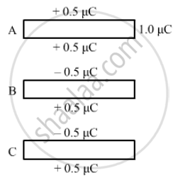
When 1µC charge is given to the upper plate, the charge gets distributed. The two sides of the upper plate have `+0.5 muC` charge. One side of the middle plate facing the upper plate has `-0.5 muC` charge and the other side has `+0.5 muC` Change . Similarly, one side of the lower plate facing the middle plate has `-0.5 muC` charge and the other side has `+0.5 muC` charge.
(a) Effective charge on the capacitor formed by the upper and middle plates = 0.5 µC
Capacitance = 50 nF = 0.05 µF
∴ Potential difference between the plates , `V = Q/C = (0.5 muC)/(0.05 muF) = 10 "V"`
(b) Effective charge on the capacitor formed by the middle and lower plates = 0.5 µC
Capacitance = 0.50 µF
∴ Potential difference between the plates, `V = Q/C = (0.5 muC)/(0.05 muF) = 10 "V"`
APPEARS IN
संबंधित प्रश्न
Define 1 volt PD.
Draw a labelled diagram of Van de Graaff generator. State its working principle to show how by introducing a small charged sphere into a larger sphere, a large amount of charge can be transferred to the outer sphere. State the use of this machine and also point out its limitations.
The potential difference applied across a given resistor is altered so that the heat produced per second increases by a factor of 9. By what factor does the applied potential difference change?
A metal rod of square cross-sectional area A having length l has current I flowing through it when a potential difference of V volt is applied across its ends (figure I). Now the rod is cut parallel to its length into two identical pieces and joined as shown in figure II. What potential difference must be maintained across the length of 2l. so that the current in the rod is still I?

Explain the principle of a device that can build up high voltages of the order of a few million volts.
Draw a schematic diagram and explain the working of Van de Graff generator device.
Is there any restriction on the upper limit of the high voltage set up in Van de Graff generator machine? Explain.
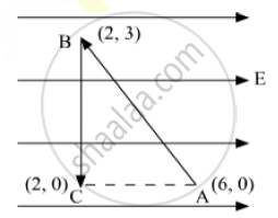
A test charge ‘q’ is moved without acceleration from A to C along the path from A to B and then from B to C in electric field E as shown in the figure. (i) Calculate the potential difference between A and C. (ii) At which point (of the two) is the electric potential more and why?
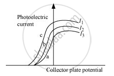
The figure shows a plot of three curves a, b, c, showing the variation of photocurrent vs collector plate potential for three different intensities I1, I2and I3 having frequencies v1, v2 and v3 respectively incident of a photosensitive surface.
Point out the two curves for which the incident radiations have same frequency but different intensities.
A 100 pF capacitor is charged to a potential difference of 24 V. It is connected to an uncharged capacitor of capacitance 20 pF. What will be the new potential difference across the 100 pF capacitor?
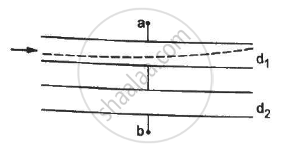
Both the capacitors shown in figure are made of square plates of edge a. The separations between the plates of the capacitors are d1 and d2 as shown in the figure. A potential difference V is applied between the points a and b. An electron is projected between the plates of the upper capacitor along the central line. With what minimum speed should the electron be projected so that it does not collide with any plate? Consider only the electric forces.
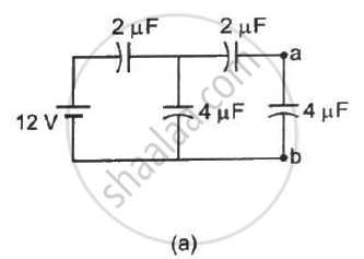
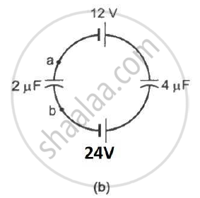
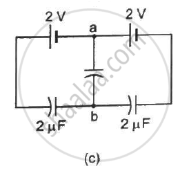
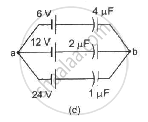
Find the potential difference `V_a - V_b` between the points a and b shown in each part of the figure.
A charge of 20 µC is placed on the positive plate of an isolated parallel-plate capacitor of capacitance 10 µF. Calculate the potential difference developed between the plates.
The capacitance between the adjacent plates shown in figure is 50 nF. A charge of 1⋅0 µC is placed on the middle plate. (a) What will be the charge on the outer surface of the upper plate? (b) Find the potential difference developed between the upper and the middle plates.
Answer the following question:
Find the expression for the resistivity of a material.
Assertion: Electric potential and electric potential energy are different quantities.
Reason: For a system of positive test charge and point charge electric potential energy = electric potential.
A bullet of mass of 2 g is having a charge of 2 µc. Through what potential difference must it be accelerated, starting from rest, to acquire a speed of 10 m/s.
Can there be a potential difference between two adjacent conductors carrying the same charge?
