Advertisements
Advertisements
प्रश्न
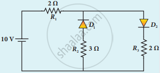
The given circuit has two ideal diodes connected as shown in the figure below. Calculate the current flowing through the resistance R1.
उत्तर
D1 will act as Reverse bias so current will not pass through it
Total Resistance = 4Ω
V = 10 V
Current flow through R1I = `"V"/"R"`
= `10/4`
= 2.5 A
APPEARS IN
संबंधित प्रश्न
The barrier potential of a p-n junction depends on
(i) type of semiconductor material
(ii) amount of doping
(iii) temperature
Which one of the following is correct?
Write a short note on diffusion current across the p-n junction.
Mention the types of biasing.
Give the principle of solar cells.
Draw the circuit diagram of a half wave rectifier and explain its working.
Explain the construction and working of a full-wave rectifier.
Explain the formation of depletion region and barrier potential in PN junction diode.
Explain the working principle of a solar cell. Mention its applications.
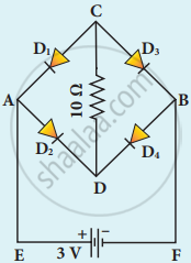
Four silicon diodes and a 10 Ω resistor are connected as shown in the figure below. Each diode has a resistance of 1 Ω. Find the current flows through the 10 Ω resistor.
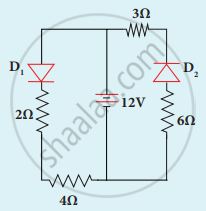
Determine the current flowing through 3 Ω and 4 Ω resistors of the circuit given below. Assume that diodes D1 and D2 are ideal diodes.