Advertisements
Advertisements
प्रश्न
Explain the working principle of a solar cell. Mention its applications.
उत्तर

Cross-sectional view of a solar cell
1. Solar cell converts light energy directly into electricity or electric potential difference by the photovoltaic effect.
2. It generates emf when radiations fall on the p-n junction. A solar cell is of two types p-type and n-type.
3. Both types use a combination of p-type and n-type silicon which together forms the p-n junction.
4. In solar cells, electron-hole pairs are generated due to the absorption of light near the junction.
5. Electrons move towards n-type silicon, holes move towards the p-type silicon layer.
6. Electrons reaching the n-side are collected by front contact and holes reaching p-side are collected by back electrical contact.
7. Thus potential difference is developed across solar cells. When an external load is connected, photocurrent flows through it.
8. Many solar cells are connected in series or parallel to form solar panels or modules.
Applications:
- Widely used in calculators, watches, toys, portable power supplies, etc.
- Used in satellites and space stations.
- Solar panels are used to generate electricity.
APPEARS IN
संबंधित प्रश्न
If a positive half-wave rectified voltage is fed to a load resistor, for which part of a cycle there will be current flow through the load?
The zener diode is primarily used as ____________.
The barrier potential of a p-n junction depends on
(i) type of semiconductor material
(ii) amount of doping
(iii) temperature
Which one of the following is correct?
A diode is called a unidirectional device. Explain.
What do you mean by leakage current in a diode?
Draw the circuit diagram of a half wave rectifier and explain its working.
What is an LED? Give the principle of its operation with a diagram.
Explain the formation of depletion region and barrier potential in PN junction diode.
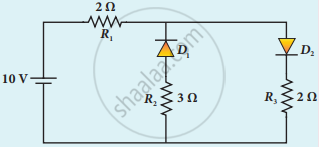
The given circuit has two ideal diodes connected as shown in the figure below. Calculate the current flowing through the resistance R1.

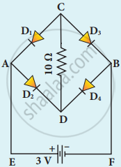
Four silicon diodes and a 10 Ω resistor are connected as shown in the figure below. Each diode has a resistance of 1 Ω. Find the current flows through the 10 Ω resistor.

