Advertisements
Advertisements
प्रश्न
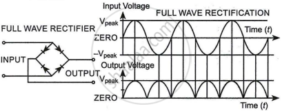
With the help of a circuit diagram, explain how a full wave rectifier gives output rectified voltage corresponding to both halves of the input ac voltage.
उत्तर
A full wave rectifier is a circuit configuration that transforms both half cycles of input alternating current (AC) to direct current (DC). As a result, a full-wave rectifier is significantly more efficient than a half-wave rectifier. A full wave rectifier is a device that converts both half cycles of the input supply (alternating current) to direct current (DC). There are two techniques to build a full wave rectifier. The first technique employs a centre-tapped transformer and two diodes.


The ends of the secondary transformer are connected to the p-side of the two diodes in this configuration.
The two-diode circuit in Figure produces output rectified voltage that corresponds to both the positive and negative halves of the alternating current cycle. It is therefore referred to as a full-wave rectifier.
The output is measured between the common point of the n-side diodes and the middle of the transformer's secondary after the n-side diodes are coupled together. As a result, the transformer is referred to as a centre-tap transformer since it has a secondary that is equipped with a centre tapping for a full-wave rectifier.
APPEARS IN
संबंधित प्रश्न
Draw the circuit diagram of a full wave rectifier. Explain its working showing its input and output waveforms.
Draw the circuit diagram of a half wave rectifier and explain its working.
When the diode shows saturated current, dynamic place resistance is _____________ .
Fill in the blank.
The ability of a junction diode to __________ an alternating voltage is based on the fact that it allows current to pass only when it is forward biased.
Explain with a proper diagram how an ac signal can be converted into dc (pulsating) signal with output frequency as double than the input frequency using pn junction diode. Give its input and output waveforms.
To reduce the ripples in a rectifier circuit with capacitor filter ______.
- RL should be increased.
- input frequency should be decreased.
- input frequency should be increased.
- capacitors with high capacitance should be used.
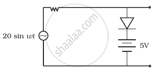
Assuming the ideal diode, draw the output waveform for the circuit given in figure. Explain the waveform.

With the help of a circuit diagram, explain briefly how a p-n junction diode works as a half-wave rectifier.
Name the device which utilizes the unilateral action of a pn diode to convert ac into dc.
Draw a labelled circuit diagram of a full wave rectifier. Show graphically how the output voltage varies with time.
