Advertisements
Advertisements
प्रश्न
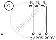
A multirange voltmeter can be constructed by using a galvanometer circuit as shown in figure. We want to construct a voltmeter that can measure 2V, 20V and 200V using a galvanometer of resistance 10Ω and that produces maximum deflection for current of 1 mA. Find R1, R2 and R3 that have to be used.
उत्तर
The galvanometer can also be used as a voltmeter to measure the voltage across a given section of the circuit. For this, a very high resistance wire is to be connected in series with galvanometer. The relationship is given by Ig (G + R) – V where Ig is the range of galvanometer, G is the resistance of galvanometer and R is the resistance of wire connected in series with galvanometer.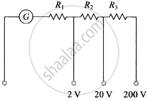
Applying expression in different situations
For `i_G (G + R_1)` = 2 for 2 V range
For `i_G (G + R_1 + R_2)` = 20 for 20 V range
And For `i_G (G + R_1 + R_2 + R_3)` = 200 for 200 V range
By solving, we get
R1 = 1990 Ω R2 = 18 kΩ and R3 = 180 kΩ.
APPEARS IN
संबंधित प्रश्न
The combined resistance of a galvanometer of resistance 500Ω and its shunt is 21Ω. Calculate the value of shunt.
Show that the current flowing through a moving coil galvanometer is directly proportional to the angle of deflection of coil.
Write the underlying principle of a moving coil galvanometer.
A galvanometer of resistance G is converted into a voltmeter to measure upto V volts by connecting a resistance R1 in series with the coil. If a resistance R2 is connected in series with it, then it can measures upto V/2 volts. Find the resistance, in terms of R1 and R2, required to be connected to convert it into a voltmeter that can read upto 2 V. Also find the resistance G of the galvanometer in terms of R1 and R2
State the principle of the working of a moving coil galvanometer, giving its labeled diagram ?
The current sensitivity of a galvanometer increase by 20%. If its resistance also increases by 25%, the voltage sensitivity will ______.
How is current sensitivity increased?
Explain in brief the basic construction of a moving-coil table galvanometer whit a neat labelled diagram.
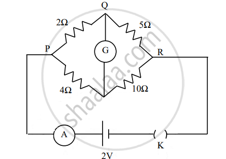
The figure below shows a circuit containing an ammeter A, a galvanometer G and a plug key K. When the key is closed: