Advertisements
Advertisements
प्रश्न
An inductor of reactance 1 Ω and a resistor of 2 Ω are connected in series to the terminals of a 6 V (rms) a.c. source. The power dissipated in the circuit is ______.
पर्याय
8 W
2 W
14.4 W
18 W
उत्तर
An inductor of reactance 1 Ω and a resistor of 2 Ω are connected in series to the terminals of a 6 V (rms) a.c. source. The power dissipated in the circuit is 14.4 W.
Explanation:
According to the problem, XL = 1 Ω, R = 2 Ω, Ems = 6 V, Pav = ?
Average power dissipated in the circuit
Pav = ErmsIrms cos `phi` .....(i)
Irms = `E_(rms)/Z`
Z = `sqrt(R^2 + X_L^2)`
= `sqrt(4 + 1) = sqrt(5)`
Irms = `6/sqrt(5) A`
`cos phi = 6/sqrt(5) A`
Pav = `6 xx 6/sqrt(5) xx 2/sqrt(5)` .....[From equation (i)]
= `72/(sqrt(5)sqrt(5)) = 72/5` = 14.4 W
APPEARS IN
संबंधित प्रश्न
An alternating emf of 220 V is applied to a circuit containing a resistor R having the resistance of 160Ω and a capacitor ‘C’ is series. The current is found to lead the supply voltage by an angle
`θ = tan^(-1) ("3/4")`
a) Calculate
1) The capacitive reactance
2) The impedance of the circuit
3) Current flowing in the circuit
b) If the frequency of the applied emf is 50 Hz, what is the value of the capacitance of the capacitor ‘C’?
The power factor of an a.c. circuit is 0.5. What is the phase difference between voltage and current in this circuit ?
Can you have an AC series circuit in which there is a phase difference of (a) 180° (b) 120° between the emf and the current?
A resistance is connected to an AC source. If a capacitor is included in the series circuit, will the average power absorbed by the resistance increase or decrease? If an inductor of small inductance is also included in the series circuit, will the average power absorbed increase or decrease further?
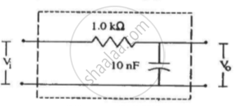
Following figure shows a typical circuit for a low-pass filter. An AC input Vi = 10 mV is applied at the left end and the output V0 is received at the right end. Find the output voltage for ν = 10 k Hz, 1.0 MHz and 10.0 MHz. Note that as the frequency is increased the output decreases and, hence, the name low-pass filter.
In previous questions 3 and 4, what is the net power absorbed by each circuit over a complete cycle. Explain your answer.
Suppose the circuit has a resistance of 15 Ω. Obtain the average power transferred to each element of the circuit, and the total power absorbed.
A 100 Ω electric iron is connected to 200 V, 50 Hz ac source. Calculate average power delivered to iron, peak power and energy spent in one minute?
In the series LCR circuit, the power dissipation is through ______
