Advertisements
Advertisements
प्रश्न
(i) Draw a clear labelled diagram of an electric bell.
(ii) Explain in brief, its working.
(iii) What material is used for the core of an electric bell? State the reason.
उत्तर
(i)

(ii) An electric bell is one of the most common applications of an electromagnet.
Construction and wiring: An electric bell shown in above fig. The main parts of the bell are:
- A horse-shoe electromagnet M, having iron core,
- Soft iron armature A,
- A hammer H,
- A gong G,
- A metallic spring strip SS,
- An adjusting screw SS,
- A switch (or bell-push) K, and
- A battery.
Working and function of each part:
The working of an electric bell is based on the magnetic effect of current. When the electric circuit is closed by pressing the switch K, the current flows through the coil CC and the core of electromagnet gets magnetized and therefore it attracts the armature A as shown A, the hammer H strikes the gong G and the bell rings.
At the moment, when the armature, due to attraction, moves towards the electromagnet, the connection between the strip SS and the screw S’ breaks which stops the flow of current in the circuit. Consequently, the electromagnet loses magnetism (i.e.r it gets demagnetized) and the armature A flies back to its original position due to the spring effect of the strip SS. Now the armature again touches the screw S’, resulting in the flow of current in the circuit. The electromagnet regains its magnetism and the armature A is again attracted, so the hammer H strikes the gong G again.
This process of make and break of the circuit goes on the hammer strikes the gong repeatedly and the bell rings so long as the switch K is kept pressed.
(iii) The core of the electromagnet is made of soft iron because: Firstly, it increases the intensity of the magnetic field of the electromagnet and secondly it easily get demagnetized when no current flows in the turns of the coil of insulated copper wire wound over the core, thus helping in the smooth working of the electric bell.
APPEARS IN
संबंधित प्रश्न
Name two factors on which the magnitude of an induced e.m.f. in the secondary coil depends.
The following diagram in Fig.10.42 shows a coil of several turns of copper wire connected to a sensitive centre zero galvanometer G near a magnet NS. The coil is free to move in the direction shown in the diagram.
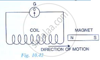
(i) Describe the observation if the coil is rapidly moved.
(ii) How would the observation be altered if (a) the coil has twice as many turns (b the coil was made to move three times as fast?
State the principle of a step-up transformer. Explain, with the help of a labeled diagram, its working ?
What is a transformer? On what principle does it work?
Name three losses of energy in a transformer. How are they minimized?
A transformer lowers e.m.f. from 220 V to 15 V. If 400 W power is given in primary, calculate (i) the current in primary coil and (ii) the current in secondary coil.
A transformer is essentially an a.c. device. It cannot work on d.c. It changes alternating voltages or currents. It does not affect the frequency of a.c. It is based on the phenomenon of mutual induction. A transformer essentially consists of two coils of insulated copper wire having different numbers of turns and wound on the same soft iron core.
The number of turns in the primary and secondary coils of an ideal transformer is 2000 and 50 respectively. The primary coil is connected to a main supply of 120 V and secondary coil is connected to a bulb of resistance 0.6 Ω.
The value of current in primary coil is ______.
The magnetic flux through a coil perpendicular to its plane is varying according to the relation Φ = (5t3 + 4t2 + 2t - 5) Weber. If the resistant of the coil is 5 ohm, then the induced current through the coil at t = 2 sec will be ______.
Explain why core of a transformer is always laminated.
