Advertisements
Advertisements
प्रश्न
The potential difference across the resistor is 160V and that across the inductor is 120V. Find the effective value of the applied voltage. If the effective current in the circuit be 1.0 A, calculate the total impedance of the circuit.
उत्तर
eL = 120 V eL = i × L
eR = 160V eR = iR
`R = e/i = 160/1 = 160 Ω `
`X_L = 120/1 = 120 Ω `
`Z = sqrt(R^2 + X_L^2 `
` = sqrt ((160)^2 + (120)^2)`
` = sqrt( 25600 + 14400)`
` = sqrt(40000)`
`Z = sqrt( 4 xx 1.4 ) = 200 Omega`
Z = 200 Ω
effecience voltage
e = iZ
e = i × 200 = 200V
APPEARS IN
संबंधित प्रश्न
A source of ac voltage v = v0 sin ωt, is connected across a pure inductor of inductance L. Derive the expressions for the instantaneous current in the circuit. Show that average power dissipated in the circuit is zero.
Find the value of t/τ for which the current in an LR circuit builds up to (a) 90%, (b) 99% and (c) 99.9% of the steady-state value.
An LR circuit with emf ε is connected at t = 0. (a) Find the charge Q which flows through the battery during 0 to t. (b) Calculate the work done by the battery during this period. (c) Find the heat developed during this period. (d) Find the magnetic field energy stored in the circuit at time t. (e) Verify that the results in the three parts above are consistent with energy conservation.
The current in a discharging LR circuit without the battery drops from 2.0 A to 1.0 A in 0.10 s. (a) Find the time constant of the circuit. (b) If the inductance of the circuit 4.0 H, what is its resistance?
Derive an expression for the average power dissipated in a series LCR circuit.
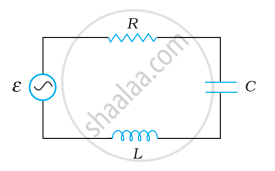
Figure shows a series LCR circuit connected to a variable frequency 230 V source. L = 5.0 H, C = 80 µF, R = 40 Ω.

- Determine the source frequency which drives the circuit in resonance.
- Obtain the impedance of the circuit and the amplitude of current at the resonating frequency.
- Determine the rms potential drops across the three elements of the circuit. Show that the potential drop across the LC combination is zero at the resonating frequency.
A series LCR circuit with L = 0.12 H, C = 480 nF, R = 23 Ω is connected to a 230 V variable frequency supply.
(a) What is the source frequency for which current amplitude is maximum. Obtain this maximum value.
(b) What is the source frequency for which average power absorbed by the circuit is maximum. Obtain the value of this maximum power.
(c) For which frequencies of the source is the power transferred to the circuit half the power at resonant frequency? What is the current amplitude at these frequencies?
(d) What is the Q-factor of the given circuit?
Obtain the resonant frequency and Q-factor of a series LCR circuit with L = 3.0 H, C = 27 µF, and R = 7.4 Ω. It is desired to improve the sharpness of the resonance of the circuit by reducing its ‘full width at half maximum’ by a factor of 2. Suggest a suitable way.
In a series LCR circuit supplied with AC, ______.
Select the most appropriate option with regard to resonance in a series LCR circuit.
