Advertisements
Advertisements
प्रश्न
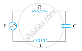
Figure shows a series LCR circuit connected to a variable frequency 230 V source. L = 5.0 H, C = 80 µF, R = 40 Ω.

- Determine the source frequency which drives the circuit in resonance.
- Obtain the impedance of the circuit and the amplitude of current at the resonating frequency.
- Determine the rms potential drops across the three elements of the circuit. Show that the potential drop across the LC combination is zero at the resonating frequency.
उत्तर
Inductance of the inductor, L = 5.0 H
Capacitance of the capacitor, C = 80 μF = 80 × 10−6 F
Resistance of the resistor, R = 40 Ω
Potential of the variable voltage source, V = 230 V
(a) Resonance angular frequency is given as:
`ω_"R" = 1/sqrt"LC"`
= `1/sqrt (5 xx 80 xx 10^-6)`
= `10^3/20`
= 50 rad s−1
Hence, the circuit will come in resonance for a source frequency of 50 rad s−1.
(b) Impedance of the circuit is given by the relation,
`"Z" = sqrt("R"^2 + (ω"L" - 1/(ω"C"))^2`
At resonance,
`ω"L" = 1/(ω"C")`
∴ Z = R = 40 Ω
Amplitude of the current at the resonating frequency is given as:
`"I"_0 = "V"_0/"Z"`
Where,
V0 = Peak voltage
= `sqrt2 "V"`
∴ `"I"_0 = (sqrt(2) "V")/"Z"`
= `(sqrt2 xx 230)/4`
= 8.13 A
Hence, at resonance, the impedance of the circuit is 40 Ω and the amplitude of the current is 8.13 A.
(c) The rms potential drop across the inductor,
`("V"_"L")_"rms" = "I" xx ω_"R""L"`
Where,
I = rms current
= `"I"_0/sqrt2`
= `(sqrt2 "V")/(sqrt2 "Z")`
= `230/40 "A"`
∴ `("V"_"L")_"rms"= 230/40 xx 50 xx 5`
= 1437.5 V
Potential drop across the capacitor,
`("V"_"c")_"rms" = "I" xx 1/(ω_"R" "C")`
= `230/40 xx 1/(50 xx 80 xx 10^-6)`
= 1437.5 V
Potential drop across the resistor,
`("V"_"R")_"rms" = "IR"`
= `230/40 xx 40`
= 230 V
Potential drop across the LC combination,
`"V"_"LC" = "I" (ω_"R" "L" - 1/(ω_"R" "C"))`
At resonance, ωRL = `1/(ω_"R""C")`
∴ VLC = 0
Hence, it is proved that the potential drop across the LC combination is zero at resonating frequency.
APPEARS IN
संबंधित प्रश्न
In a series LCR circuit connected to an a.c. source of voltage v = vmsinωt, use phasor diagram to derive an expression for the current in the circuit. Hence, obtain the expression for the power dissipated in the circuit. Show that power dissipated at resonance is maximum
Why does current in a steady state not flow in a capacitor connected across a battery? However momentary current does flow during charging or discharging of the capacitor. Explain.
The time constant of an LR circuit is 40 ms. The circuit is connected at t = 0 and the steady-state current is found to be 2.0 A. Find the current at (a) t = 10 ms (b) t = 20 ms, (c) t = 100 ms and (d) t = 1 s.
An inductor-coil of resistance 10 Ω and inductance 120 mH is connected across a battery of emf 6 V and internal resistance 2 Ω. Find the charge which flows through the inductor in (a) 10 ms, (b) 20 ms and (c) 100 ms after the connections are made.
An LR circuit with emf ε is connected at t = 0. (a) Find the charge Q which flows through the battery during 0 to t. (b) Calculate the work done by the battery during this period. (c) Find the heat developed during this period. (d) Find the magnetic field energy stored in the circuit at time t. (e) Verify that the results in the three parts above are consistent with energy conservation.
The current in a discharging LR circuit without the battery drops from 2.0 A to 1.0 A in 0.10 s. (a) Find the time constant of the circuit. (b) If the inductance of the circuit 4.0 H, what is its resistance?
What will be the potential difference in the circuit when direct current is passed through the circuit?

Draw a labelled graph showing a variation of impedance of a series LCR circuit with frequency of the a.c. supply.
A series LCR circuit with L = 0.12 H, C = 480 nF, R = 23 Ω is connected to a 230 V variable frequency supply.
(a) What is the source frequency for which current amplitude is maximum. Obtain this maximum value.
(b) What is the source frequency for which average power absorbed by the circuit is maximum. Obtain the value of this maximum power.
(c) For which frequencies of the source is the power transferred to the circuit half the power at resonant frequency? What is the current amplitude at these frequencies?
(d) What is the Q-factor of the given circuit?
In a series LCR circuit supplied with AC, ______.
In series LCR circuit, the phase angle between supply voltage and current is ______.
At resonant frequency the current amplitude in series LCR circuit is ______.
In an LCR circuit having L = 8 henery. C = 0.5 µF and R = 100 ohm in series, the resonance frequency in radian/sec is
If the rms current in a 50 Hz ac circuit is 5 A, the value of the current 1/300 seconds after its value becomes zero is ______.
A coil of 0.01 henry inductance and 1 ohm resistance is connected to 200 volt, 50 Hz ac supply. Find the impedance of the circuit and time lag between max. alternating voltage and current.
A series RL circuit with R = 10 Ω and L = `(100/pi)` mH is connected to an ac source of voltage V = 141 sin (100 πt), where V is in volts and t is in seconds. Calculate
- the impedance of the circuit
- phase angle, and
- the voltage drop across the inductor.
When an alternating voltage of 220V is applied across device X, a current of 0.25A flows which lags behind the applied voltage in phase by π/2 radian. If the same voltage is applied across another device Y, the same current flows but now it is in phase with the applied voltage.
- Name the devices X and Y.
- Calculate the current flowing in the circuit when the same voltage is applied across the series combination of X and Y.
A series LCR circuit is connected to an ac source. Using the phasor diagram, derive the expression for the impedance of the circuit.
