Advertisements
Advertisements
प्रश्न
If the rms current in a 50 Hz ac circuit is 5 A, the value of the current 1/300 seconds after its value becomes zero is ______.
पर्याय
`5sqrt(2)` A
`5sqrt(3/2)` A
`5/6` A
`5/sqrt(2)` A
उत्तर
If the rms current in a 50 Hz ac circuit is 5 A, the value of the current 1/300 seconds after its value becomes zero is `underline(5sqrt(3/2) A)`.
Explanation:
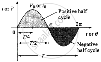
Equation for i and V: Alternating current or voltage varying as sine function can be written as
`i = i_0 sin ωt = i_0 sin 2piv t = i_0 sin (2pi)/T t`

And `V = V_0 sin ωt = V_0 sin 2pivt = V_0 sin (2pi)/T t`
Where I and V are instantaneous values of current and voltage,
i0 and V0 are peak values of current and voltage
ω = Angular frequency on rad/sec, v = Frequency in Hz
T = TIme peroid
`I_(ωt) = I = sqrt(2)I_0 = 5sqrt(2)A`
`I = I_0 sin ωt`
At `t = 1/300 sec, I = 5sqrt(2) sin 2 pivt = 5sqrt(2) sin 2pi xx 50 xx 1/300`
= `5sqrt(2) sin pi/3 = 5sqrt(2) sin 60^circ`
= `52 - sqrt(3)sqrt(2)` = 532
= `5sqrt(3/2) A`
APPEARS IN
संबंधित प्रश्न
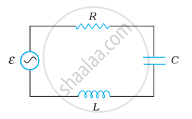
A voltage V = V0 sin ωt is applied to a series LCR circuit. Derive the expression for the average power dissipated over a cycle. Under what condition (i) no power is dissipated even though the current flows through the circuit, (ii) maximum power is dissipated in the circuit?
The time constant of an LR circuit is 40 ms. The circuit is connected at t = 0 and the steady-state current is found to be 2.0 A. Find the current at (a) t = 10 ms (b) t = 20 ms, (c) t = 100 ms and (d) t = 1 s.
An inductor of inductance 2.00 H is joined in series with a resistor of resistance 200 Ω and a battery of emf 2.00 V. At t = 10 ms, find (a) the current in the circuit, (b) the power delivered by the battery, (c) the power dissipated in heating the resistor and (d) the rate at which energy is being stored in magnetic field.
The potential difference across the resistor is 160V and that across the inductor is 120V. Find the effective value of the applied voltage. If the effective current in the circuit be 1.0 A, calculate the total impedance of the circuit.
Figure shows a series LCR circuit connected to a variable frequency 230 V source. L = 5.0 H, C = 80 µF, R = 40 Ω.

- Determine the source frequency which drives the circuit in resonance.
- Obtain the impedance of the circuit and the amplitude of current at the resonating frequency.
- Determine the rms potential drops across the three elements of the circuit. Show that the potential drop across the LC combination is zero at the resonating frequency.
A series LCR circuit with L = 0.12 H, C = 480 nF, R = 23 Ω is connected to a 230 V variable frequency supply.
(a) What is the source frequency for which current amplitude is maximum. Obtain this maximum value.
(b) What is the source frequency for which average power absorbed by the circuit is maximum. Obtain the value of this maximum power.
(c) For which frequencies of the source is the power transferred to the circuit half the power at resonant frequency? What is the current amplitude at these frequencies?
(d) What is the Q-factor of the given circuit?
Which of the following components of an LCR circuit, with a.c. supply, dissipates energy?
Which of the following combinations should be selected for better tuning of an LCR circuit used for communication?
For an LCR circuit driven at frequency ω, the equation reads
`L (di)/(dt) + Ri + q/C = v_i = v_m` sin ωt
- Multiply the equation by i and simplify where possible.
- Interpret each term physically.
- Cast the equation in the form of a conservation of energy statement.
- Integrate the equation over one cycle to find that the phase difference between v and i must be acute.
Draw the impedance triangle for a series LCR AC circuit and write the expressions for the impedance and the phase difference between the emf and the current.
