Advertisements
Advertisements
प्रश्न
Three circuits, each consisting of a switch 'S' and two capacitors, are initially charged, as shown in the figure. After the switch has been closed, in which circuit will the charge on the left-hand capacitor
(i) increase,
(ii) decrease, and
(iii) remains the same? Give reasons.

उत्तर
When charged capacitors are connected to each other then the charge will flow from the capacitor with higher potential towards the capacitor with lower potential until a common potential is reached.
(a) In fig. (a) the potential of both the capacitor is same so the charge on left hand capacitor remains the same.
(b) In fig. (b) the potential of left hand capacitor is high so charge from 6Q to 3Q. Therefore charge on left hand capacitor will decrease. (c) In fig.
(c) the potential of left hand capacitor is low so charge will flow from 3Q to 6Q. Therefore charge on the left-hand capacitor will increase.
APPEARS IN
संबंधित प्रश्न
Define capacitor reactance. Write its S.I units.
A parallel plate capacitor of capacitance C is charged to a potential V. It is then connected to another uncharged capacitor having the same capacitance. Find out the ratio of the energy stored in the combined system to that stored initially in the single capacitor.
Three capacitors having capacitances 20 µF, 30 µF and 40 µF are connected in series with a 12 V battery. Find the charge on each of the capacitors. How much work has been done by the battery in charging the capacitors?
Take `C_1 = 4.0 "uF" and C_2 = 6.0 "uF"` in figure . Calculate the equivalent capacitance of the combination between the points indicated.

A parallel-plate capacitor of plate area A and plate separation d is charged to a potential difference V and then the battery is disconnected. A slab of dielectric constant K is then inserted between the plates of the capacitor so as to fill the space between the plates. Find the work done on the system in the process of inserting the slab.
Obtain the expression for energy stored in the parallel plate capacitor.
Three capacitors 2µF, 3µF, and 6µF are joined in series with each other. The equivalent capacitance is ____________.
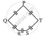
Five capacitor each of capacitance value C are connected as shown in the figure. The ratio of capacitance between P to R, and the capacitance between P and Q is ______.

Read the following paragraph and answer the questions.
| A capacitor is a system of two conductors separated by an insulator. The two conductors have equal and opposite charges with a potential difference between them. The capacitance of a capacitor depends on the geometrical configuration (shape, size and separation) of the system and also on the nature of the insulator separating the two conductors. They are used to store charges. Like resistors, capacitors can be arranged in series or parallel or a combination of both to obtain the desired value of capacitance. |
- Find the equivalent capacitance between points A and B in the given diagram.

- A dielectric slab is inserted between the plates of the parallel plate capacitor. The electric field between the plates decreases. Explain.
- A capacitor A of capacitance C, having charge Q is connected across another uncharged capacitor B of capacitance 2C. Find an expression for (a) the potential difference across the combination and (b) the charge lost by capacitor A.
OR
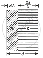
Two slabs of dielectric constants 2K and K fill the space between the plates of a parallel plate capacitor of plate area A and plate separation d as shown in the figure. Find an expression for the capacitance of the system.
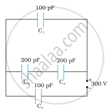
Obtain the equivalent capacitance of the network shown in the figure. For a 300 V supply, determine the charge on each capacitor.

