Advertisements
Advertisements
Question
An a.c. source of voltage V = V0 sin ωt is connected to a series combination of L, C, and R. Use the phasor diagram to obtain the expression for an impedance of a circuit and the phase angle between voltage and current. Find the condition when current will be in phase with the voltage. What is the circuit in this condition called?
Solution
i)

Voltage of the source is given as
I0→" data-mce-style="position: relative;">V=V0sinωtI0→
Let current of the source be " data-mce-style="position: relative;">I=I0sinωt
The maximum voltage across R is `vec(V_R)=vec(V_0)R` represented along OX.
The maximum voltage across L is `vec(V_L)=vec(I_0) X_L`represented along OY and is 90° ahead of `vec(I_0)`
The maximum voltage across C is `vec(V_C)=vec(I_0) X_C`represented along OC and is lagging behind `vec(I_0)`by 900
The voltage across L and C has a phase difference of 180°
Hence, reactive voltage is`vec(V_L)-vec(V_C)`represented by OB
The vector sum of`vec(V_R), vec(V_L) "and "vec(V_C)`resultant of OA and OB', represented along OK
`OK=V_0=sqrt(OA^2+OB^2)`
`=>V_0=sqrt(V_R2+(V_L-V_C)^2)=sqrt(I_0R^2+(I_0X-V_C)^2)`
`=>V_0=I_0sqrt(R^2+(X_L-X_C)^2)`
The impedance can be calculated as follows:
`Z=V_0/I_0=sqrt(R^2+(X_L-X_C)^2)`
When XL = XC, the voltage and current are in the same phase. In such a situation, the circuit is known as the non-inductive circuit.
RELATED QUESTIONS
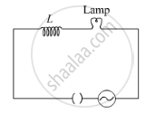
A lamp is connected in series with an inductor and an AC source. What happens to the brightness of the lamp when the key is plugged in and an iron rod is inserted inside the inductor? Explain.
The current in a discharging LR circuit is given by i = i0 e−t/τ , where τ is the time constant of the circuit. Calculate the rms current for the period t = 0 to t = τ.
In a series LCR circuit with an AC source, R = 300 Ω, C = 20 μF, L = 1.0 henry, εrms = 50 V and ν = 50/π Hz. Find (a) the rms current in the circuit and (b) the rms potential difference across the capacitor, the resistor and the inductor. Note that the sum of the rms potential differences across the three elements is greater than the rms voltage of the source.
What is the value of power factor for a pure resistor connected to an alternating current source ?
Answer the following question.
Show that an ideal inductor does not dissipate power in an ac circuit.
The power factor in a circuit connected to an A.C. The value of power factor is ______.
Quality factor and power factor both have the dimensions of ______.
Which of the following quantities remains constant in a step-down Transformer?
An inductor of reactance 1 Ω and a resistor of 2 Ω are connected in series to the terminals of a 6 V (rms) a.c. source. The power dissipated in the circuit is ______.
