Advertisements
Advertisements
प्रश्न
An a.c. source of voltage V = V0 sin ωt is connected to a series combination of L, C, and R. Use the phasor diagram to obtain the expression for an impedance of a circuit and the phase angle between voltage and current. Find the condition when current will be in phase with the voltage. What is the circuit in this condition called?
उत्तर
i)

Voltage of the source is given as
I0→" data-mce-style="position: relative;">V=V0sinωtI0→
Let current of the source be " data-mce-style="position: relative;">I=I0sinωt
The maximum voltage across R is `vec(V_R)=vec(V_0)R` represented along OX.
The maximum voltage across L is `vec(V_L)=vec(I_0) X_L`represented along OY and is 90° ahead of `vec(I_0)`
The maximum voltage across C is `vec(V_C)=vec(I_0) X_C`represented along OC and is lagging behind `vec(I_0)`by 900
The voltage across L and C has a phase difference of 180°
Hence, reactive voltage is`vec(V_L)-vec(V_C)`represented by OB
The vector sum of`vec(V_R), vec(V_L) "and "vec(V_C)`resultant of OA and OB', represented along OK
`OK=V_0=sqrt(OA^2+OB^2)`
`=>V_0=sqrt(V_R2+(V_L-V_C)^2)=sqrt(I_0R^2+(I_0X-V_C)^2)`
`=>V_0=I_0sqrt(R^2+(X_L-X_C)^2)`
The impedance can be calculated as follows:
`Z=V_0/I_0=sqrt(R^2+(X_L-X_C)^2)`
When XL = XC, the voltage and current are in the same phase. In such a situation, the circuit is known as the non-inductive circuit.
संबंधित प्रश्न
In a series LR circuit, XL = R and power factor of the circuit is P1. When capacitor with capacitance C such that XL = XC is put in series, the power factor becomes P2. Calculate P1/P2
Define the quality factor in an a.c. circuit. Why should the quality factor have high value in receiving circuits? Name the factors on which it depends.
A series AC circuit has a resistance of 4 Ω and a reactance of 3 Ω. The impedance of the circuit is
Transformers are used ______.
In an AC series circuit, the instantaneous currt is zero when the instantaneous voltage is maximum. Connected to the source may be a
(a) pure inductor
(b) pure capacitor
(c) pure resistor
(d) combination of an inductor and a capacitor
The current in a discharging LR circuit is given by i = i0 e−t/τ , where τ is the time constant of the circuit. Calculate the rms current for the period t = 0 to t = τ.
In a series LCR circuit with an AC source, R = 300 Ω, C = 20 μF, L = 1.0 henry, εrms = 50 V and ν = 50/π Hz. Find (a) the rms current in the circuit and (b) the rms potential difference across the capacitor, the resistor and the inductor. Note that the sum of the rms potential differences across the three elements is greater than the rms voltage of the source.
Following figure shows a typical circuit for a low-pass filter. An AC input Vi = 10 mV is applied at the left end and the output V0 is received at the right end. Find the output voltage for ν = 10 k Hz, 1.0 MHz and 10.0 MHz. Note that as the frequency is increased the output decreases and, hence, the name low-pass filter.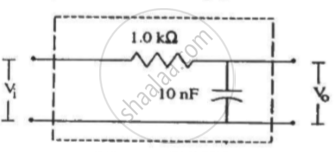
Which of the following quantities remains constant in a step-down Transformer?
A 100 Ω electric iron is connected to 200 V, 50 Hz ac source. Calculate average power delivered to iron, peak power and energy spent in one minute?
