Advertisements
Advertisements
Question
In a series LCR circuit with an AC source, R = 300 Ω, C = 20 μF, L = 1.0 henry, εrms = 50 V and ν = 50/π Hz. Find (a) the rms current in the circuit and (b) the rms potential difference across the capacitor, the resistor and the inductor. Note that the sum of the rms potential differences across the three elements is greater than the rms voltage of the source.
Solution
Given:
Resistance in series LCR circuit, R = 300 Ω
Capacitance in series LCR circuit, C = 20 μF= 20 × 10−6 F
Inductance in series LCR circuit, L = 1 Henry
RMS value of voltage, εrms = 50 V
Frequency of source, f = 50/ ` pi`Hz
Reactance of the inductor (XL) is given by,
`X_C = omegaL = 2pifL`
`rArr X_C = 500 Ω`
(a) Impedance of an LCR circuit (Z) is given by,
`Z = sqrt(R^2 + (X_C - X_L )^2 `
`rArr Z = sqrt((300)^2 + (500 - 100)^2`
`rArr Z = sqrt((300)^2 + (400)^2`
⇒ Z = 500
RMS value of current Irms is given
`I_{rms} = epsilon_{rms}/Z`
`rArr I_{rms} = 50/500`
`rArr I_{rms} = 0.1A`
(b) Potential across the capacitor `(V_C)` is given by,
`V_C = I_{rms} xx X_C`
`rArr V_C = 0.1xx500 = 50V`
Potential difference across the resistor `(V_R)` is given by
`V_R =I_{rms}xxR`
`V_R = 0.1xx300xx = 30V`
Potential difference across the inductor `(V_L)` is given by,
`V_L = I_{rms]xxXL`
` rArr V_L =0.1xx100 = 10V `
R.M.s potential = 50V
Net sum of all the potential drops = 50 V + 30 V + 10 V = 90 V
Sum of the potential drops > RMS potential applied
APPEARS IN
RELATED QUESTIONS
When an AC source is connected to an ideal inductor show that the average power supplied by the source over a complete cycle is zero.
In a series LR circuit, XL = R and power factor of the circuit is P1. When capacitor with capacitance C such that XL = XC is put in series, the power factor becomes P2. Calculate P1/P2
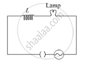
A lamp is connected in series with an inductor and an AC source. What happens to the brightness of the lamp when the key is plugged in and an iron rod is inserted inside the inductor? Explain.

Prove theoretically the relation between e.m.f. induced in a coil and rate of change of magnetic flux in electromagnetic induction.
An A.C. generator generating an emf of ε = 300 sin (100 πt) V is connected to a series combination of 16μ F capacitor, 1 H inductor and 100 Ω resistor.
Calculate :
1) An impedance of the circuit at the given frequency.
2) Resonant frequency `f_0`
3)Power factor at the resonant frequency `f_0`.
A resistance is connected to an AC source. If a capacitor is included in the series circuit, will the average power absorbed by the resistance increase or decrease? If an inductor of small inductance is also included in the series circuit, will the average power absorbed increase or decrease further?
In an AC series circuit, the instantaneous currt is zero when the instantaneous voltage is maximum. Connected to the source may be a
(a) pure inductor
(b) pure capacitor
(c) pure resistor
(d) combination of an inductor and a capacitor
Consider the situation of the previous problem. Find the average electric field energy stored in the capacitor and the average magnetic field energy stored in the coil.
Answer the following question.
Show that an ideal inductor does not dissipate power in an ac circuit.
Suppose the circuit has a resistance of 15 Ω. Obtain the average power transferred to each element of the circuit, and the total power absorbed.
Quality factor and power factor both have the dimensions of ______.
The power factor of series LCR circuit when at resistance is
Which of the following quantities remains constant in a step-down Transformer?
The series combination of R, L, C is connected to an a.c. source. If the resistance is 3 and the reactance is 4, the power factor of the circuit is:
In the series LCR circuit, the power dissipation is through ______
The coefficient of induction of a choke coil is 0.1 H and resistance is 12 Ω. If it is connected to an a.c source of frequency 60Hz. Then the power factor will be ______.
An alternating current I = 14 sin (100 πt) A passes through a series combination of a resistor of 30 Ω and an inductor of `(2/(5pi))` H. Taking `sqrt2` = 1.4 calculate the power factor of the circuit.
