Advertisements
Advertisements
Question
Prove theoretically the relation between e.m.f. induced in a coil and rate of change of magnetic flux in electromagnetic induction.
Solution
1)

Magnetic flux Φ = NABcos ωt
N → No.s of turns
A → Area of a coil
B → Magnetic field {external}
ω → Angular speed of the coil
`:. max phi_0 = NAB, omegat -> 0`
`:.phi = phi_0 cos omegat`
induce EMF(e)
e = `-(dphi)/(dt) = + omegaNAB sin omegat`
`e_0 = omegaNAB, omegat -> 90`
`:. e = e_0 sin omegat`
So there is phase difference of `pi/2` with `phi` and e
APPEARS IN
RELATED QUESTIONS
An a.c. source of voltage V = V0 sin ωt is connected to a series combination of L, C, and R. Use the phasor diagram to obtain the expression for an impedance of a circuit and the phase angle between voltage and current. Find the condition when current will be in phase with the voltage. What is the circuit in this condition called?
Ajit had a high tension tower erected on his farm land. He kept complaining to the authorities to remove it as it was occupying a large portion of his land. His uncle, who was a teacher, explained to him the need for erecting these towers for efficient transmission of power. As Ajit realised its significance, he stopped complaining.
Answer the following questions:
(a) Why is it necessary to transport power at high voltage?
(b) A low power factor implies large power loss. Explain.
(c) Write two values each displayed by Ajit and his uncle.
An A.C. generator generating an emf of ε = 300 sin (100 πt) V is connected to a series combination of 16μ F capacitor, 1 H inductor and 100 Ω resistor.
Calculate :
1) An impedance of the circuit at the given frequency.
2) Resonant frequency `f_0`
3)Power factor at the resonant frequency `f_0`.
The power factor of an a.c. circuit is 0.5. What is the phase difference between voltage and current in this circuit ?
For a given a.c., i = im sin ωt, show that the average power dissipated in a resistor R over a complete cycle is `1/2I_m^2` R .
Transformers are used ______.
The current in a discharging LR circuit is given by i = i0 e−t/τ , where τ is the time constant of the circuit. Calculate the rms current for the period t = 0 to t = τ.
A coil has a resistance of 10 Ω and an inductance of 0.4 henry. It is connected to an AC source of 6.5 V, `30/pi Hz`. Find the average power consumed in the circuit.
In a series LCR circuit with an AC source, R = 300 Ω, C = 20 μF, L = 1.0 henry, εrms = 50 V and ν = 50/π Hz. Find (a) the rms current in the circuit and (b) the rms potential difference across the capacitor, the resistor and the inductor. Note that the sum of the rms potential differences across the three elements is greater than the rms voltage of the source.
Consider the situation of the previous problem. Find the average electric field energy stored in the capacitor and the average magnetic field energy stored in the coil.
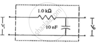
Following figure shows a typical circuit for a low-pass filter. An AC input Vi = 10 mV is applied at the left end and the output V0 is received at the right end. Find the output voltage for ν = 10 k Hz, 1.0 MHz and 10.0 MHz. Note that as the frequency is increased the output decreases and, hence, the name low-pass filter.
What is the value of power factor for a pure resistor connected to an alternating current source ?
Answer the following question.
Show that an ideal inductor does not dissipate power in an ac circuit.
In which of the following circuits the maximum power dissipation is observed?
The power factor of series LCR circuit when at resistance is
The average power dissipation in a pure capacitor in A.C circuit is
Which of the following quantities remains constant in a step-down Transformer?
The power factor of an a.c circuit having resistance R and inductance L Connected in series to an a.c source of angular frequency co is.
In an AC. circuit, the current is :
i = `5 sin (100t - pi/2)` amp.
and the a.c. potentiol is:
V = 200 sin (100t) volt.
Then the power consumption is
In the series LCR circuit, the power dissipation is through ______
An alternating current generator has an internal resistance Rg and an internal reactance Xg. It is used to supply power to a passive load consisting of a resistance Rg and a reactance XL. For maximum power to be delivered from the generator to the load, the value of XL is equal to ______.
An inductor of reactance 1 Ω and a resistor of 2 Ω are connected in series to the terminals of a 6 V (rms) a.c. source. The power dissipated in the circuit is ______.
