Advertisements
Advertisements
Question
Determine the current in each branch of the network shown in figure.

Solution
Current flowing through various branches of the circuit is represented in the given figure.
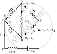
I1 = Current flowing through the outer circuit
I2 = Current flowing through branch AB
I3 = Current flowing through branch AD
I2 − I4 = Current flowing through branch BC
I3 + I4 = Current flowing through branch CD
I4 = Current flowing through branch BD
For the closed-circuit ABDA, the potential is zero i.e.,
10 I2 + 5 I4 − 5 I3 = 0
2 I2 + I4 − I3 = 0
I3 = 2 I2 + I4 ....(1)
For the closed-circuit BCDB, the potential is zero i.e.,
5(I2 − I4) − 10(I3 + I4) − 5I4 = 0
5 I2 + 5 I4 − 10 I3 − 10 I4 − 5 I4 = 0
5 I2 − 10 I3 − 20 I4 = 0
I2 = 2 I3 + 4 I4 .....(2)
For the closed circuit ABCFEA, potential is zero i.e.,
−10 + 10 (I1) + 10 (I2) + 5(I2 − I4) = 0
10 = 15 I2 + 10 I1 − 5 I4
3 I2 + 2 I1 − I4 = 2 ....(3)
From equations (1) and (2), we obtain
I3 = 2(2 I3 + 4 I4) + I4
I3 = 4 I3 + 8 I4 + I4
−3 I3 = 9 I4
−3 I4 = + I3 ....(4)
Putting equation (4) in equation (1), we obtain
I3 = 2 I2 + I4
− 4 I4 = 2 I2
I2 = −2 I4 ....(5)
It is evident from the given figure that,
I1 = I3 + I2 ....(6)
Putting equation (6) in equation (1), we obtain
3 I2 + 2(I3 + I2) − I4 = 2
5 I2 + 2 I3 − I4 = 2 .....(7)
Putting equations (4) and (5) in equation (7), we obtain
5(−2 I4) + 2(−3 I4) − I4 = 2
− 10 I4 − 6 I4 − I4 = 2
17 I4 = −2
I4 = `(-2)/17"A"`
Equation (4) reduces to
I3 = −3(I4)
= `-3((-2)/17)`
= `6/17"A"`
I2 = −2(I4)
= `-2((-2)/17)`
= `4/17"A"`
`"I"_2 - "I"_4 = 4/17 - ((-2)/17)`
= `6/17"A"`
`"I"_3 + "I"_4 = 6/17 + ((-2)/17)`
= `4/17 "A"`
I1 = I3 + I2
= `6/17 + 4/17`
= `10/17"A"`
Therefore, current in branch AB = `4/17"A"`
In branch BC = `6/17"A"`
In branch CD = `(-4)/17"A"`
In branch AD = `6/17"A"`
In branch BD = `((-2)/17)"A"`
Total current = `4/17 + 6/17 + (-4)/17 + 6/17 + (-2)/17`
= `10/17"A"`
APPEARS IN
RELATED QUESTIONS
Kirchhoff's junction law is equivalent to .............................
(a) conservation of energy.
(b) conservation of charge
(c) conservation of electric potential
(d) conservation of electric flux
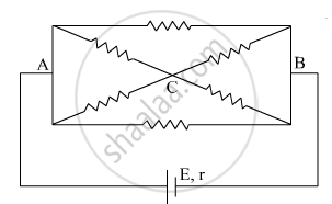
The current is drawn from a cell of emf E and internal resistance r connected to the network of resistors each of resistance r as shown in the figure. Obtain the expression for
- the current draw from the cell and
- the power consumed in the network.
State Kirchhoff's rules and explain on what basis they are justified.
Given the resistances of 1 Ω, 2 Ω, 3 Ω, how will be combine them to get an equivalent resistance of (6/11) Ω?
State Kirchhoff's rules for an electric network. Using Kirchhoff's rules, obtain the balance condition in terms of the resistances of four arms of Wheatstone bridge.
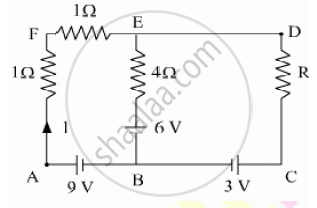
Using Kirchhoff’s rules determine the value of unknown resistance R in the circuit so that no current flows through 4 Ω resistance. Also find the potential difference between A and D.
Twelve wires, each of equal resistance r, are joined to form a cube, as shown in the figure. Find the equivalent resistance between the diagonally-opposite points a and f.

A copper wire of 10-6 m2 area of cross-section, carries a current of 2 A. If the number of electrons per cubic meter is 8 × 1028, calculate the current density and average drift velocity.
A potentiometer wire has a length of 4 m and resistance of 20 Ω. It is connected in series with resistance of 2980 Ω and a cell of emf 4 V. Calculate the potential along the wire.
Kirchhoff’s second law is a consequence of law of conservation of ______.
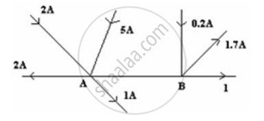
Figure shows current in a part of an electrical circuit. Then current I is ______.
Assertion: Kirchhoff’s junction rule follows from conservation of charge.
Reason: Kirchhoff’s loop rule follows from conservation of momentum.
The Kirchhoff's second law (ΣiR = ΣE), where the symbols have their usual meanings, is based on ______.
Two cell of 1.25 V and 0.75 V are connected parallel. The effective voltage will be:-
Three resistors having resistances r1, r2 and r3 are connected as shown in the given circuit. The ratio `i_3/i_1` of currents in terms of resistances used in the circuit is: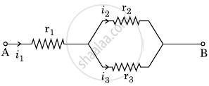
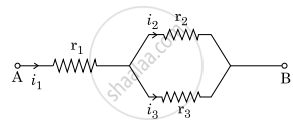
Three resistors having resistances r1, r2 and r3 are connected as shown in the given circuit. The ratio `"i"_3/"i"_1` of currents in terms of resistances used in the circuit is :
Power P is to be delivered to a device via transmission cables having resistance RC. If V is the voltage across R and I the current through it, find the power wasted and how can it be reduced.
The circuit in figure shows two cells connected in opposition to each other. Cell E1 is of emf 6V and internal resistance 2Ω; the cell E2 is of emf 4V and internal resistance 8Ω. Find the potential difference between the points A and B.
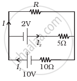
Two cells of voltage 10V and 2V and internal resistances 10Ω and 5Ω respectively, are connected in parallel with the positive end of 10V battery connected to negative pole of 2V battery (Figure). Find the effective voltage and effective resistance of the combination.
A 6-volt battery is connected to the terminals of a three-metre-long wire of uniform thickness and resistance of 100 ohms. The difference of potential between two points on the wire separated by a distance of 50 cm will be ______.
