Advertisements
Advertisements
Question
Draw the circuit diagram of zener diode as a voltage regulator and briefly explains its working ?
Solution
Zener diode as voltage regulator

-
After the break down voltage, a small change in the voltage across the zener diode produces a large change in the current through the circuit.
-
If the voltage is increased beyond the zener voltage, then the resistance of the zener diode drops considerably.
-
A zener diode and a resistor are connected to a fluctuating DC supply such that the zener diode is reverse biased.
- When the voltage across the diode tends to increase, the current through the diode rises out of proportion and causes a sufficient increase in voltage drop across the resistor. Therefore, the O/P voltage lowers back to normal.
RELATED QUESTIONS
Describe, with the help of a circuit diagram, the working of Zener diode as a voltage regulator.
What is Zener diode?
Draw the I − V characteristics of zener diode and explain briefly how reverse current suddenly increase at the breakdown voltage.
Describe briefly with the help of a circuit diagram how a zener diode works to obtain a constant dc voltage from the unregulated dc output of a rectifier ?
Voltage applied between cathode and anode of an X-ray tube is 18 kV. Calculate the minimum wavelength of the X-rays produced.
In the circuit shown in the figure, the potential barrier for Ge diode is 0.3 V and for Si diode it is 0.7 V. What is the voltage VA?

Electronic motors operating at low voltages tend to burn out because
Consider the following statements (A) and (B) and identify the correct answer.
- A zener diode is connected in reverse bias, when used as a voltage regulator.
- The potential barrier of p-n junction lies between 0.1 V to 0.3 V.
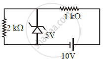
In connection with the circuit drawn below, the value of current flowing through 2 kΩ resistor is ______ × 10-4 A.
The reverse breakdown voltage of a Zener diode is 5.6 V in the given circuit.
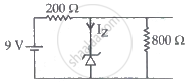
The current Iz through the Zener is ______.
