Advertisements
Advertisements
Question
Explain with the help of a labelled circuit diagram how you will find the resistance of a combination of three resistors, or resistance R1, R2 and R3, joined in parallel. Also mention how you will connect the ammeter and the voltmeter in the circuit when measuring the current in the circuit and the potential difference across one of the three resistors of the combination.
Solution

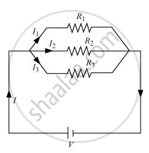
The given figure shows a circuit consisting of three resistors R1, R2 and R3 connected in parallel. The total current in the circuit (I) gets divided among the three resistors as I1, I2 and I3.
Thus,
I = I1 + I2 + I3
Applying Ohm’s law to each resistor,
`I_1=V/R_1`
`I_2=V/R_2`
`I_3=V/R_3`
Let the equivalent resistance of the circuit be Req.
Applying Ohm’s law to the equivalent circuit,
`I=V/R_(eq)`
Using these,
`V/R_(eq)=V/R_1+V/R_2+V/R_3`
`1/R_(eq)=1/R_1+1/R_2+1/R_3`
An ammeter has to be connected in series with the combination of all three resistors so that the current passes through the ammeter becomes equal to the total current through the circuit.
The voltmeter has to be connected in parallel to that resistor across which the potential difference has to be measured.
APPEARS IN
RELATED QUESTIONS
Draw a schematic diagram of a circuit consisting of a battery of three cells of 2 V each, a 5 Ω resistor, an 8 Ω resistor, and a 12 Ω resistor, and a plug key, all connected in series.
Draw circuit symbols for variable resistance
Draw circuit symbols for
a cell
Draw the labelled diagram of an electric circuit comprising of a cell, a resistance, an ammeter, a voltmeter and a closed switch (or closed plug key). Which of the two has a large resistance : an ammeter or a voltmeter?
A device that is used to break an electric circuit is called ______.
Draw a circuit diagram of an electric circuit containing a cell, a key, an ammeter, a resistor of 2Ω in series with a combination of two resistors (4Ω each) in parallel and a voltmeter across the parallel combination. Will the potential difference across the 2Ω resistor be the same as that across the parallel combination of 4Ω resistors? Give reason.
Observe the circuit given:
1. Would any of the bulbs glow when the switch is in the ‘OFF’ position?

2. What will be the order in which the bulbs A, B, and C will glow when the switch is moved to the ‘ON’ position?

In the above circuit, if the current reading in the ammeter A is 2A, what would be the value of R1?
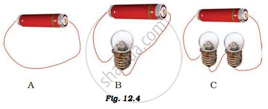
In which of the following circuits A, B, and C gave in Fig. 12.4, the cell will be used up very rapidly?

Write a short note on the different electrical circuits.
