Topics
Chemical Substances - Nature and Behaviour (Chemistry)
Chemical Reactions and Equations
- Chemical Equation
- Balancing Chemical Equation
- Types of Chemical Change or Chemical Reaction
- Direct Combination (or Synthesis) Reaction
- Decomposition Reactions
- Single Displacement Reactions
- Double Displacement Reaction
- Oxidation, Reduction and Redox Reactions
- Corrosion of Metals
- Rancidity of Food and Its Prevention
World of Living (Biology)
Acids, Bases and Salts
- Acids
- Bases (Alkalis)
- Indicators
- Properties of Acids
- Properties of Bases (Alkalis)
- Acid or a Base in a Water Solution
- Similarities and Differences Between Acids and Bases
- Strength of Acidic or Basic Solutions
- Salts
- Important Salts in Daily Life
- Preparation and Uses of Sodium Hydroxide
- Preparation and Uses of Bleaching Powder
- Preparation and Uses of Baking Soda
- Preparation and Uses of Washing Soda
- Preparation and Uses of Plaster of Paris
Metals and Non Metals
- Types of Element: Metals
- Physical Properties of Metals
- Chemical Properties of Metal
- Types of Element: Non-metal
- Physical Properties of Non-metal
- Chemical Properties of Non-metal
- Ionic or Electrovalent Bond
- Reactivity Series of Metals
- Extraction of Reactive Metals
- Refining of Metals
- Corrosion of Metals
- The Covalent Bond
- Prevention of Corrosion
Natural Phenomena (Physics)
Carbon and its Compounds
- Carbon: a Versatile Element
- The Covalent Bond
- Saturated and Unsaturated Carbon Compounds
- Allotropy and Allotropes of Carbon
- Crystalline Allotropes of Carbon: Diamond
- Crystalline Allotropes of Carbon: Graphite
- Crystalline Allotropes of Carbon: Fullerene
- Chains, Branches and Rings of Carbon Compound
- Functional Groups in Carbon Compounds
- Homologous Series of Carbon Compound
- Nomenclature of Organic Compounds
- Properties of Carbon
- Ethanol
- Ethanoic Acid
- Soap
- Detergents
- Cleansing Action of Soap
Effects of Current (Physics)
Life Processes
- Living Organisms and Life Processes
- Nutrients and Nutrition
- Mode of Nutrition in Plant
- Autotrophic Plants
- Heterotrophic Plants
- Different Ways of Taking Food
- Human Digestive System
- The Mouth and Buccal Cavity
- The Teeth and Its Structure
- The Salivary Glands
- Swallowing and Peristalsis
- The Food Pipe/Oesophagus
- The Stomach
- The Small Intestine
- Pancreas
- Absorption of Food
- The Large Intestine
- Assimilation of Food
- Liver
- Respiration
- Respiration
- Breathing in Other Animals
- Osmoregulation
- Types of Respiration: Aerobic and Anaerobic Respiration
- Human Respiratory System
- Circulation in Animals
- Blood
- Composition of Blood: Plasma (The Liquid Portion of Blood)
- Composition of Blood: Red Blood Cells (Erythrocytes)
- Composition of Blood: White Blood Cells (Leukocytes)
- Composition of Blood: Blood Platelets (Thrombocytes)
- Blood Circulatory System in Human
- Human Heart
- Blood Vessels
- Circulation of Blood in the Heart (Functioning of Heart)
- Types of Closed Circulation
- Heart Beat - Heart Sounds "LUBB" and "DUP"
- Function of Platelets - Clotting of Blood (Coagulation)
- Lymph and Lymphatic System
- Blood Pressure (B.P.)
- Transport System in Plants
- Water absorbing organ
- Translocation of Water (Ascent of Sap)
- Transport of Mineral Ions
- Transport of Food
- Transpiration
- Excretion
- Human Excretory System
- Function of the Kidney - “Production of Urine”
- Excretion
Natural Resources
Periodic Classification of Elements
- History of Periodic Table: Early Attempts at the Classification of Elements
- Dobereiner’s Triads
- Newland's Law of Octaves
- Mendeleev’s Periodic Table
- Merits and Demerits of Mendeleev’s Periodic Table
- The Modern Periodic Table
- Periodic Properties
- Valency
- Atomic Radius Or Atomic Size
- Metallic and Non-metallic Characters
Control and Co-ordination
- Control and Co-ordination in Human Being
- Human Nervous System
- Neuron (Or Nerve Cell) and Its Types
- Neuron (Or Nerve Cell) and Its Types
- Nerve Fibres
- Major Division of the Nervous System
- Central Nervous System (CNS)
- Peripheral Nervous System (PNS)
- The Human Brain - Forebrain
- The Human Brain - Forebrain
- Reflex and Reflex Action
- Nervous Pathways in Reflexes
- Reflex Arc
- Coordination in Plant: Tropism in Plants
- Chemical Coordination
- Plant Hormones
- Types of Plant Hormones: Auxins
- Types of Plant Hormones: Gibberellins
- Types of Plant Hormones: Ethylene
- Types of Plant Hormones: Cytokinins
- Types of Plant Hormones: Abscisic Acid (ABA)
- Types of Plant Hormones: Ethylene
- Hormones in Animals
- Human Endocrine System
- Pituitary Gland or Hypophysis Gland
- Thyroid Gland
- Parathyroid Gland
- Pancreas (Islets of Langerhans)
- Adrenal Gland (Suprarenal Gland)
- Reproductive Glands (Gonads)
- Thymus Gland
Internal assessment
How do Organisms Reproduce?
- Accumulation of Variation During Reproduction
- Reproduction
- Mode of Reproduction in Plant
- Asexual Reproduction in Plant
- Natural Vegetative Reproduction
- Sexual Reproduction in Flowering Plants
- Sexual Reproduction in Animals
- Human Reproduction
- The Male Reproductive System
- The Female Reproductive System
- Menstrual Cycle (Ovarian Cycle)
- Reproductive Health
- Sexually Transmitted Diseases (STD)
Heredity
- Accumulation of Variation During Reproduction
- Heredity or Inheritance
- Gregor Johann Mendel – Father of Genetics
- Monohybrid Cross
- Gregor Johann Mendel – Father of Genetics
- Mendelian Inheritance - Mendel’s Law of Heredity
- Sex Determination
- Organic Evolution
- Lamarck’s Theory of Evolution
- Darwinism
- Theories of Origin of Life
- Speciation
- Evolution and Classiffication
- Evidences for Biological Evolution
- Paleobotany
- Evolution by Stages
- Human Evolution
Light - Reflection and Refraction
- Reflection of Light
- Law of Reflection of Light
- Mirrors
- Plane Mirror
- Spherical Mirrors
- Rules for the Construction of Image Formed by a Spherical Mirror
- Images Formed by Spherical Mirrors
- Concave Mirror
- Image Formation by Concave Mirror
- Convex Mirror
- Image Formation by Convex Mirror
- Sign Convention
- Mirror Equation/Formula
- Linear Magnification (M) Due to Spherical Mirrors
- Introduction to Refraction of Light
- Refraction of Light Through a Rectangular Glass Slab
- Refractive Index
- Spherical Lens
- Images Formed by Sperical Lenses
- Guideline for Image Formation Due to Refraction Through a Convex and Concave Lens
- Concave Lens
- Images Formed by Concave Lenses
- Convex Lens
- Images Formed by Convex Lenses
- Sign Convention
- Lens Formula
- Magnification Due to Spherical Lenses
- Power of a Lens
The Human Eye and the Colourful World
- Human Eye
- Working of the Human Eye
- Eye Defect and Its Correction: Myopia Or Near-sightedness
- Eye Defect and its Correction: Hypermetropia or Far-sightedness
- Eye Defect and Its Correction: Presbyopia
- Care of the Eyes
- Refraction of Light Through a Prism
- Prism
- Dispersion of Light Through Prism and Formation of Spectrum
- Atmospheric Refraction
- Application of Atmospheric Refraction
- Scattering of Light and Its Types
- Applications of Scattering of Light
Electricity
- Electricity
- Electric Current
- Electric Circuit
- Potential and Potential Difference
- Symbols and Functions of Various Components of an Electric Circuits
- Ohm's Law (V = IR)
- Factors Affecting the Resistance of a Conductor
- Electrical Resistivity and Electrical Conductivity
- Resistors in Series
- Resistors in Parallel
- Effects of Electric Current
- Heating Effect of Electric Current
- Electrical Power
Magnetic Effects of Electric Current
- Magnetic Effect of Electric Current
- Magnetic Field
- Properties of magnetic lines of force
- Magnetic Field Due to a Current Carrying Straight Conductor
- Right-hand Thumb Rule
- Magnetic Field Due to Current in a Loop (Or Circular Coil)
- Magnetic Field Due to a Current Carving Cylindrical Coil (or Solenoid)
- Force on a Current Carrying Conductor in a Magnetic Field
- Electric Motor
- Electromagnetic Induction
- Faraday's Laws of Electromagnetic Induction
- Electric Generator
- Alternating Current (A.C.) Generator
- Direct Current Motor
- Household Electrical Circuits
- Distinction Between an A.C. Generator and D.C. Motor
- Types of Current
Our Environment
Sources of Energy
- Source of Energy
- Conventional energy resources or non-renewable energy resources
- Fossil Fuels
- Heat Energy (Thermal Energy)
- Hydroelectric Energy
- Bio-energy
- Wind Energy
- Solar Energy
- Solar Energy Devices
- Energy from the Sea
- Geothermal Energy
- Nuclear Energy
- Nuclear Fission
- Forms of Energy
- Environmental Consequences
- How Long Will an Energy Source Last Us?
Sustainable Management of Natural Resources
- Sustainability of Natural Resources
- Case Study: Ganga Pollution and Ganga Action Plan
- Solid Waste Management
- Five R’s of Waste Management
- Protecting our environment
- Forests: Our Lifeline
- Stakeholders of Forest
- Conservation of Forest
- Conservation of Wildlife
- Water Management (Conservation of Water)
- Fresh Water Management
- Non-crystalline/Amorphous Forms: Coal
- Petroleum
- Conservation of Coal, Petroleum, and Natural Resources
- Overview of Natural Resource Management
- Introduction
- Working
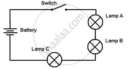
- Electric Circuits and Circuit Diagrams
- Experiment
- Joule’s Law of Heating and Electrical Power
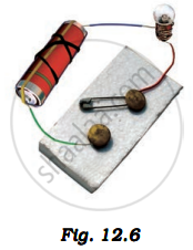
Introduction:
An electric circuit is a setup that allows electric current to flow through connected components, making devices work, like lighting up a bulb.
Components of the Circuit:
- Cell holder: This holds the dry cells (batteries) that provide the energy needed for the current.
- Electric bulb: lights up when current flows through it.
- Plug key: acts like a switch that can open or close the circuit.
- Wires: Connect all the components, allowing the current to travel through them.
A circuit diagram is a graphical representation of an electrical circuit. A schematic diagram shows the components and interconnections of the circuit using standardised symbolic representations, while a pictorial circuit diagram uses simple images of components.
| Components | Symbol |
| 1. An electric cell | 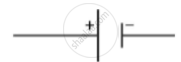 |
| 2. A battery or a combination of cells | |
| 3. Plug key or switch (open) | |
| 4. Plug key or switch (closed) | |
| 5. A wire joint | |
| 6. Wires crossing without joining |  |
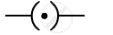
| 7. Electric bulb | |
| 8. A resistor of resistance R | |
| 9. Variable resistance or rheostat | |
| 10. Ammeter | |
| 11. Voltmeter |
Working:
- Closing the plug key completes the circuit after fitting the dry cell in the cell holder (Fig. a) and connecting the components as shown in Fig. b.
- Once the plug key is closed, electric current flows from the cell through the wires to the bulb, making it light up.
- The circuit breaks if you remove the cell or open the plug key. This stops the current, and the bulb goes off.
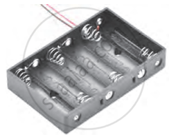
(a) Cell holder
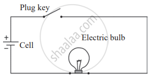
(b) Simple electric circuit
Electric Circuits and Circuit Diagrams:
An electric circuit is a continuous path that allows electric current to flow. It consists of conducting wires, a cell (or battery), and other components like resistors, all connected in a loop. Electric circuits study or utilise the current flow, measure electrical quantities such as current and voltage, and regulate the operation of electrical devices. A circuit diagram shows the arrangement of components in a circuit. And it uses special symbols to represent components like resistors, batteries, wires, ammeters, and voltmeters.
Components in the Circuit:
- Electric Cell: Provides the potential difference required to drive current through the circuit.
- Ammeter: Connected in series with the circuit to measure the current flowing through it.
- Voltmeter: Connected in parallel with the resistor to measure the potential difference across it.
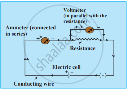
Electrical Circuit
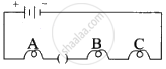
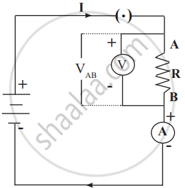
Experiment
1. Aim: To study the transfer of electrical energy in a circuit and verify Joule’s Law of Heating.
2. Requirements: Connecting wires, electric cells (battery), electrical resistor (R), voltmeter (V), ammeter (A), and plug key (switch).
3. Procedure
Set up the circuit as shown in the diagram, ensuring all components are properly connected.
Close the switch to allow current (I) to flow through the circuit.
Measure the current (I) using the ammeter.
Measure the potential difference (VAB) across the resistor using the voltmeter.
Observe energy transfer:
- The potential at point A is higher than at point B, as A is connected to the positive terminal of the cell.
- As charge (Q) moves from A to B, electrical energy (VAB × Q) is supplied by the battery to the resistor.
- The resistor converts electrical energy into heat, increasing its temperature.
Electric circuit
Key Equations:
Electrical Power: P = VAB × I
Heat Produced (Joule’s Law of Heating): H = I2 × R × t
4. Conclusion: The experiment shows that a resistor converts electrical energy into heat, following Joule’s Law of Heating. The amount of heat produced depends on the current, resistance, and time for which the current flows. The unit of electrical power is 1 watt (W), defined as 1 joule per second.
Joule’s Law of Heating and Electrical Power:
Joule’s law explains how electrical energy is converted into heat energy when an electric current flows through a resistor. The heat produced depends on the voltage, current, and resistance of the circuit.
Electrical Power and Heat Generation:
1. Definition of Electrical Power
Electrical power (P) is the rate at which electrical energy is supplied to a circuit. It is given by:
\[\mathrm{P=Electrical~power=\frac{Energy}{Timerequired}=\frac{V_{AB}Q}{t}=V_{AB}I}\]
where VAB is the potential difference across the resistor, I is the current, and Q is the charge.
2. Heat Produced in a Resistor
The energy supplied by the cell in time t is:
H = P × t = VAB × I × t
By Ohm’s Law:
VAB = I × R
Substituting this in the heat equation:
\[\mathrm{H}=\mathrm{V}_{\mathrm{AB}}^{2}\times\frac{\mathrm{t}}{\mathrm{R}}\]
or
H = I × I × R × t = I2 × R × t
This equation is known as Joule’s Law of Heating, which states that the heat produced in a resistor is directly proportional to the square of the current, resistance, and time.
3. Unit of Electrical Power
Electrical power is also expressed as:
P = VAB × I = Volt × Ampere
Since 1 Volt × 1 Ampere is equal to:
\[\begin{array}
{cc}1\text{Volt x 1 Amp}= & \frac{1\mathrm{J}}{1\mathrm{C}}\mathrm{x}\frac{1\mathrm{C}}{1\mathrm{s}}
\end{array}\]
\[\begin{array}
{rl}\frac{1\mathrm{J}}{1\mathrm{s}} & =\mathrm{W}\left(\mathrm{watt}\right)
\end{array}\]
The unit of electrical power is 1 Watt (W), which means 1 Joule of energy is consumed per second.