Advertisements
Advertisements
Question
Give reason/short answer.
In the given circuit diagram two resistors are connected to a 5V supply.

A third resistor is now connected in parallel with 6Ω resistor. Will the potential difference across the 8Ω resistor the larger, smaller, or the same as before? Explain the reason for your answer.
Solution
Potential difference across 8Ω resistor will be larger.
Reason: As per the question, the new circuit diagram will be
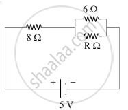
When any resistor is connected parallel to 6Ω resistance. Then the resistance across that branch (6Ω and RΩ) will become less than 6Ω. i.e., the equivalent resistance of the entire circuit will decrease and hence current will increase. Since, V = IR, the potential difference across 8Ω resistor will be larger.
APPEARS IN
RELATED QUESTIONS
Calculate force per unit length acting on the wire B due to the current flowing in the wire A.(See
Figure 2 below)

Two metallic wires, P1 and P2 of the same material and same length but different cross-sectional areas, A1 and A2 are joined together and connected to a source of emf. Find the ratio of the drift velocities of free electrons in the two wires when they are connected (i) in series, and (ii) in parallel.
A wheel with 8 metallic spokes each 50 cm long is rotated with a speed of 120 rev/min in a plane normal to the horizontal component of the Earth’s magnetic field. The Earth’s magnetic field at the place is 0.4 G and the angle of dip is 60°. Calculate the emf induced between the axle and the rim of the wheel. How will the value of emf be affected if the number of spokes were increased?
Answer the following question.
Two bulbs are rated (P1, V) and (P2, V). If they are connected (i) in series and (ii) in parallel across a supply V, find the power dissipated in the two combinations in terms of P1 and P2.
100 cells each of emf 5 V and internal resistance 1 Ω are to be arranged so as to produce maximum current in a 25 Ω resistance. Each row contains equal number of cells. The number of rows should be ______.
Choose the correct alternative.
Five dry cells each of voltage 1.5 V are connected as shown in the diagram

What is the overall voltage with this arrangement?
Give reason/short answer.
In the given circuit diagram two resistors are connected to a 5V supply.

Calculate potential difference across the 8Ω resistor.
Two cells of 1.25 V and 0.75 V are connected in series with anode of one connected to anode of the other. The effective voltage will be ______.
Two metal wires of identical dimensions are connected in parallel. If σ1 and σ2 are the conductivities of the metal wires respectively, the effective conductivity of the combination is
If two bulbs of wattages 25 W and 100 W respectively each rated by 220 V are connected in series with the supply of 440 v·then which bulb will fuse?
When cells are connected in parallel, then ______
Two cells of emf’s approximately 5V and 10V are to be accurately compared using a potentiometer of length 400 cm.
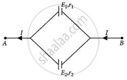
Two cells of emfs E1 and E2 and internal resistances r1 and r2 respectively are connected in parallel as shown in the figure. Deduce the expression for the
- equivalent emf of the combination
- equivalent internal resistance of the combination
- potential difference between the points A and B.
The equivalent resistance of series combination of two resistors is 's'. When they are connected in parallel, the equivalent resistance is 'p'. If s = np, then the minimum value for n is ______. (Round off to the Nearest Integer)
Five identical cells each of internal resistance 1Ω and emf 5V are connected in series and in parallel with an external resistance 'R'. For what value of 'R', current in series and parallel combination will remain the same?
Two cells of emf E1 and E2 and internal resistances r1 and r2 are connected in parallel, with their terminals of the same polarity connected together. Obtain an expression for the equivalent emf of the combination.
A 60 Ω resistor, a 1.0 H inductor and a 4 μF capacitor are connected in series to an ac supply generating an emf e = 300 sin (500t) V. Calculate:
- impedance of the circuit.
- peak value of the current flowing through the circuit.
- phase difference between the current and the supply voltage.
