Advertisements
Advertisements
Question
How much is the potential difference between live and neutral wires?
Solution
The potential difference between live and neutral wires is around 220 V.
APPEARS IN
RELATED QUESTIONS
Draw a schematic diagram of a circuit consisting of a battery of three cells of 2 V each, a 5 Ω resistor, an 8 Ω resistor, and a 12 Ω resistor, and a plug key, all connected in series.
Redraw the circuit of question 1, putting in an ammeter to measure the current through the resistors and a voltmeter to measure the potential difference across the 12 Ω resistors. What would be the readings in the ammeter and the voltmeter?
Explain with the help of a labelled circuit diagram how you will find the resistance of a combination of three resistors, or resistance R1, R2 and R3, joined in parallel. Also mention how you will connect the ammeter and the voltmeter in the circuit when measuring the current in the circuit and the potential difference across one of the three resistors of the combination.
Explain the construction and working of the following. Draw a neat diagram and label it.
Electric motor
Two tungsten bulbs of power 50 W and 60 W work on 220 V potential difference. If they are connected in parallel, how much current will flow in the main conductor?
The following figure shows the symbols for components used in the accompanying electrical circuit. Place them at proper places and complete the circuit.

Which law can you prove with the help of above circuit?
In an electric circuit, electron flow a from of point of ______ potential to the point of ______ potential.
In an electric circuit, a battery and a bulb have been connected and the battery consists of two cells of equal potential difference. If the bulb is not glowing, then which tests will you perform in order to find out the reason for the bulb not glowing?
Answer the following question.
With the help of a suitable circuit diagram prove that the reciprocal of the equivalent resistance of a group of resistances joined in parallel is equal to the sum of the reciprocals of the individual resistances.
Draw a neat diagram showing a closed electric circuit.
Explain the following:
Closed circuit
Increasing the current passing through the wire decreases the magnetic field intensity.
Nowadays MCBs are used in homes, for stop the current in the circuit which suddenly increases.
The switch is used to close or open an electric circuit.
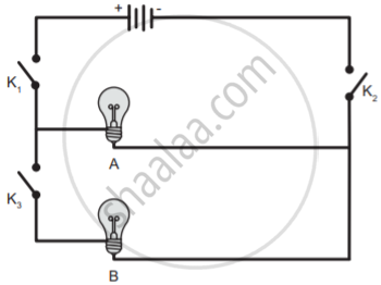
In the given circuit diagram, which of the given switch(s) should be closed. So that only bulb A glows.
Rahul wants to make an electric circuit. He has a bulb, two wires, a safety pin, and a piece of copper. He does not have any electric cell or battery. Suddenly he gets some idea. He uses lemon instead of a battery and makes a circuit. Will the bulb glow?
In which among the following circuits does the bulb glow?
Draw the circuit diagram for the following series connection
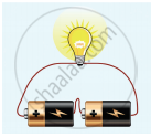
Fuse is
When a circuit is open, _____ cannot pass through it.
A device that is used to break an electric circuit is called ______.
Assertion: In an open circuit, the current passes from one terminal of the electric cell to another.
Reason: Generally, the metal disc of a cell acts as a positive terminal.
______ is a kind of fish which is able to produce an electric current.
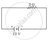
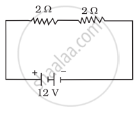
In the following circuits (Figure), heat produced in the resistor or combination of resistors connected to a 12 V battery will be
 |
 |
 |
| (i) | (ii) | (iii) |
In an electric circuit a fuse is a _________ _______ to prevent possible fire.
Draw the symbols of the following circuit components.
switch in off position
The ______ is a species of fish that can give electric shocks of up to six hundred fifty watts of electricity.
Paheli is running short of connecting wires. To complete an electric circuit, she may use a
In which of the following circuits A, B, and C gave in Fig. 12.4, the cell will be used up very rapidly?
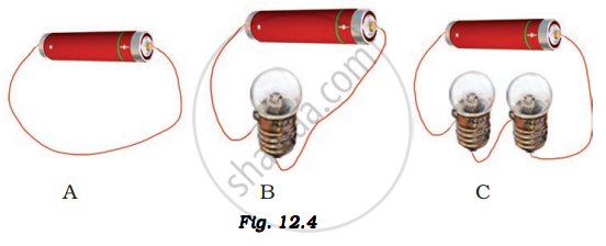
Boojho has a cell and a single piece of connecting wire. Without cutting the wire in two, will he be able to make the bulb glow? Explain with the help of a circuit diagram.
Write a short note on the different electrical circuits.
Name the device which is used to measure the strength of the electric current in an electric circuit.
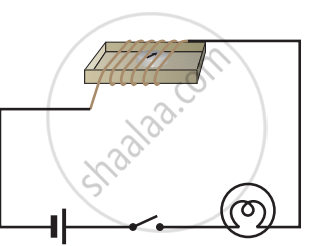
Set up the circuit shown in Figure again. Move the key to ‘ON’ position and watch carefully in which direction the compass needle gets deflected. Switch ‘OFF’ the current. Now keeping rest of the circuit intact, reverse the connections at the terminal of the cell. Again switch ‘on’ the current. Note the direction in which the needle gets deflected. Think of an explanation.
