Advertisements
Advertisements
Question
Show that in an AC circuit containing a pure inductor, the voltage is ahead of current by π/2 in phase.
Solution
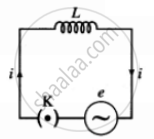
The diagram below depicts an alternating current source generating a voltage e = e0 sin wt and connecting it to a key K and a pure inductor of inductance L to form a closed circuit.

An AC source connected to an inductor
When the key K is closed, an emf is induced in the inductor as the magnetic flux associated with it changes over time. This emf opposes the applied emf, and we have, according to Faraday and Lenz's laws of electromagnetic induction,
`"e'" = - "L""di"/"dt"` ....(1)
The induced emf is e', while the current through the inductor is i. To keep the current flowing, e and e' must have the same magnitude but opposing directions.
According to Kirchhoff's voltage law, as the resistance of the inductor is assumed to be zero, we have, e = -e' = L`"di"/"dt"` ....(2)
∴ `"di"/"dt" = "e"/"L" = ("e"_0 sin omega"t")/"L"`
∴ `int "di" = int ("e"_0 sin omega"t")/"L" "dt"`
∴ i = `- "e"_0/(omega"L") cos omega"t" + "C"`
where C is the integration constant. C must be time-independent and have a current dimension. Because e oscillates around zero, I must similarly oscillate around zero, and so no time independent component of current can exist.
∴ C = 0
∴ i = - `"e"_0/(omega "L") cos omega"t" = - "e"_0/(omega"L") sin (pi/2 - omega"t")`
∴ i = `"e"_0/(omega"L") sin (omega"t" - pi/2)` .....(3)
as sin (- θ) = - sin θ
From Eq. (3), `"i"_"peak" = "i"_0 = "e"_0/(omega "L")`
∴ i = `"i"_0 sin (omega"t" - pi/2)` .....(4)
When this equation is compared to e = e0 sin wt, it is seen that e leads i by π/2 rad, indicating that the voltage is π/2 rad ahead of the current in phase.
APPEARS IN
RELATED QUESTIONS
The magnetic field energy in an inductor changes from maximum to minimum value in 5.0 ms when connected to an AC source. The frequency of the source is
An inductor, a resistance and a capacitor are joined in series with an AC source. As the frequency of the source is slightly increased from a very low value, the reactance
An inductor coil of some resistance is connected to an AC source. Which of the following quantities have zero average value over a cycle?
(a) Current
(b) Induced emf in the inductor
(c) Joule heat
(d) Magnetic energy stored in the inductor
An inductance of 2.0 H, a capacitance of 18μF and a resistance of 10 kΩ is connected to an AC source of 20 V with adjustable frequency.
(a) What frequency should be chosen to maximize the current in the circuit?
(b) What is the value of this maximum current?
A coil of inductance 0.50 H and resistance 100 Ω is connected to a 240 V, 50 Hz ac supply.
(a) What is the maximum current in the coil?
(b) What is the time lag between the voltage maximum and the current maximum?
Obtain if the circuit is connected to a high-frequency supply (240 V, 10 kHz). Hence, explain the statement that at very high frequency, an inductor in a circuit nearly amounts to an open circuit. How does an inductor behave in a dc circuit after the steady state?
A 100 µF capacitor in series with a 40 Ω resistance is connected to a 110 V, 60 Hz supply.
(a) What is the maximum current in the circuit?
(b) What is the time lag between the current maximum and the voltage maximum?
Obtain if the circuit is connected to a 110 V, 12 kHz supply? Hence, explain the statement that a capacitor is a conductor at very high frequencies. Compare this behaviour with that of a capacitor in a dc circuit after the steady state.
An applied voltage signal consists of a superposition of a dc voltage and an ac voltage of high frequency. The circuit consists of an inductor and a capacitor in series. Show that the dc signal will appear across C and the ac signal across L.
Alternating current is so called because _______.
In a circuit containing resistance only, voltage and current are ______.
If circuit containing inductance only, the current ______.
If the frequency of an A.C. is made 4 times of its initial value, the inductive reactance will ______.
A current of 4A flows in a coil when connected to a 12V dc source. If the same coil is connected to a 12V, 50 rad/s a.c. source, a current of 2.4A flows in the circuit. Determine the inductance of the coil.
An inductive circuit contains resistance of 10 ohms and an inductance of 2 henry. If an A.C. voltage of 120 Volts and frequency 60 Hz is applied to this circuit, the current would be nearly ______.
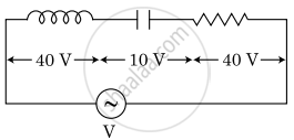
An inductor of inductance L, a capacitor of capacitance C and a resistor of resistance ‘R’ are connected in series to an ac source of potential difference ‘V’ volts as shown in the figure.
The potential difference across L, C, and R is 40 V, 10 V and 40 V, respectively. The amplitude of the current flowing through the LCR series circuit is `10sqrt2 "A"`. The impedance of the circuit is:

Explain why the reactance offered by an inductor increases with increasing frequency of an alternating voltage.
An electrical device draws 2kW power from AC mains (voltage 223V (rms) = `sqrt(50,000)` V). The current differs (lags) in phase by `phi(tan phi = (-3)/4)` as compared to voltage. Find (i) R, (ii) XC – XL, and (iii) IM. Another device has twice the values for R, XC and XL. How are the answers affected?
An ideal inductor is connected across an AC source of voltage. The current in the circuit ______.
What is the ratio of inductive and capacitive reactance in an ac circuit?
