Advertisements
Advertisements
प्रश्न
A battery of emf 100 V and a resistor of resistance 10 kΩ are joined in series. This system is used as a source to supply current to an external resistance R. If R is not greater than 100 Ω, the current through it is constant up to two significant digits.
Find its value. This is the basic principle of a constant-current source.
उत्तर
Given:-
Emf of the battery, E = 100 volt
Resistance in series with battery, R' = 10 kΩ = 10000 Ω
External resistance, R = (1-100) Ω
When no external resistor is present (R = 0), current through the circuit,
\[i = \frac{E}{R'} = \frac{100}{1000} = 0 . 01 \text{ Amp.}\]
When R = 1 Ω,
\[i = \frac{100}{10000 + 1} = \frac{100}{10001}\]
\[ = 0 . 009999 A\]
When R = 100 Ω,
\[i = \frac{100}{10000 + 100}\]
\[ = \frac{100}{10100} = 0 . 009900 A\]
We can see that up to R = 100 Ω, the current does not change up to two significant digits.
APPEARS IN
संबंधित प्रश्न
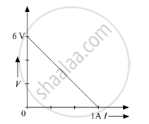
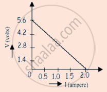
The plot of the variation of potential difference across a combination of three identical cells in series, versus current is shown below. What is the emf and internal resistance of each cell ?
Two identical cells of emf 1.5 V each joined in parallel, supply energy to an external circuit consisting of two resistances of 7 Ω each joined in parallel. A very high resistance voltmeter reads the terminal voltage of cells to be 1.4 V. Calculate the internal resistance of each cell.
A cell of emf 'E' and internal resistance 'r' is connected across a variable resistor 'R'. Plot a graph showing variation of terminal voltage 'V' of the cell versus the current 'I'. Using the plot, show how the emf of the cell and its internal resistance can be determined.
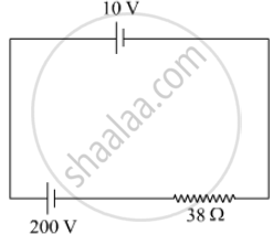
A 10 V cell of negligible internal resistance is connected in parallel across a battery of emf 200 V and internal resistance 38 Ω as shown in the figure. Find the value of current in the circuit.
Plot a graph showing variation of voltage vs the current drawn from the cell. How can one get information from this plot about the emf of the cell and its internal resistance?
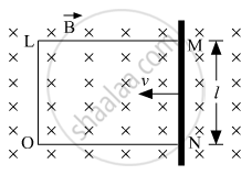
A rectangular conductor LMNO is placed in a uniform magnetic field of 0.5 T. The field is directed perpendicular to the plane of the conductor. When the arm MN of length of 20 cm is moved towards left with a velocity of 10 ms−1, calculate the emf induced in the arm. Given the resistance of the arm to be 5 Ω (assuming that other arms are of negligible resistance) find the value of the current in the arm.
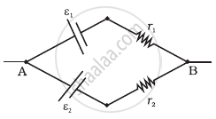
Two cells of emf E1, E2 and internal resistance r1 and r2 respectively are connected in parallel as shown in the figure.

Deduce the expressions for
(1) the equivalent e.m.f of the combination
(2) the equivalent resistance of the combination, and
(3) the potential difference between the point A and B.
Two non-ideal batteries are connected in series. Consider the following statements:-
(A) The equivalent emf is larger than either of the two emfs.
(B) The equivalent internal resistance is smaller than either of the two internal resistances.
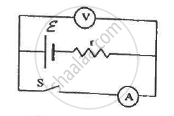
The following figure shows an arrangement to measure the emf ε and internal resistance r of a battery. The voltmeter has a very high resistance and the ammeter also has some resistance. The voltmeter reads 1.52 V when the switch S is open. When the switch is closed, the voltmeter reading drops to 1.45 V and the ammeter reads 1.0 A. Find the emf and the internal resistance of the battery.
Answer the following question.
A cell of emf E and internal resistance r is connected across a variable resistor R. Plot the shape of graphs showing a variation of terminal voltage V with (i) R and (ii) circuit current I.
A conductor of length 'l' is rotated about one of its ends at a constant angular speed 'ω' in a plane perpendicular to a uniform magnetic field B. Plot graphs to show variations of the emf induced across the ends of the conductor with (i) angular speed ω and (ii) length of the conductor l.
A cell having an emf E and internal resistance r is connected across a variable external resistance R. As the resistance R is increased, the plot of potential difference V across R is given by ______.
A straight line plot showing the terminal potential difference (V) of a cell as a function of current (I) drawn from it, is shown in the figure. The internal resistance of the cell would be then ______.
The internal resistance of a cell is the resistance of ______
Two batteries of emf ε1 and ε2 (ε2 > ε1) and internal resistances r1 and r2 respectively are connected in parallel as shown in figure.
A battery of EMF 10V sets up a current of 1A when connected across a resistor of 8Ω. If the resistor is shunted by another 8Ω resistor, what would be the current in the circuit? (in A)
Three cells, each of emf E but internal resistances 2r, 3r and 6r are connected in parallel across a resistor R.
Obtain expressions for (i) current flowing in the circuit, and (ii) the terminal potential differences across the equivalent cell.
