Advertisements
Advertisements
प्रश्न
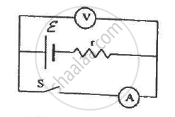
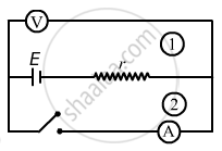
The following figure shows an arrangement to measure the emf ε and internal resistance r of a battery. The voltmeter has a very high resistance and the ammeter also has some resistance. The voltmeter reads 1.52 V when the switch S is open. When the switch is closed, the voltmeter reading drops to 1.45 V and the ammeter reads 1.0 A. Find the emf and the internal resistance of the battery.

उत्तर
(a) 
When the switch S is opened, loop 2 will be open and no current will pass through the ammeter. Loop 1 will be closed; so, a current will flow through it. But since the voltmeter has very high resistance, compared to the internal resistance of the battery, the voltage-drop across the internal resistance can be ignored, compared to the voltage drop across the voltmeter. So, the voltage appearing across the voltmeter will be almost equal to the emf of the battery.
∴ ε = 1.52 V
(b) When the switch is closed, current will pass through the circuit in loop 2. In this case, there will be a voltage drop across r due to current i flowing through it.
Applying the loop rule, we get:-
ε – ir = 1.45
⇒ 1.52 – ir = 1.45
⇒ ir = 0.07
⇒ 1.r = 0.07
r = 0.07 Ω
APPEARS IN
संबंधित प्रश्न
Two cells of emfs 1.5 V and 2.0 V, having internal resistances 0.2 Ω and 0.3 Ω, respectively, are connected in parallel. Calculate the emf and internal resistance of the equivalent cell.
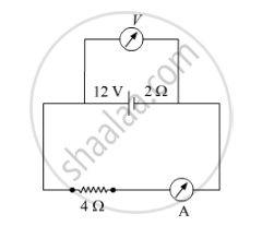
A battery of emf 12 V and internal resistance 2 Ω is connected to a 4 Ω resistor as shown in the figure.
(a) Show that a voltmeter when placed across the cell and across the resistor, in turn, gives the same reading.
(b) To record the voltage and the current in the circuit, why is voltmeter placed in parallel and ammeter in series in the circuit?

A cell of emf 'E' and internal resistance 'r' is connected across a variable resistor 'R'. Plot a graph showing variation of terminal voltage 'V' of the cell versus the current 'I'. Using the plot, show how the emf of the cell and its internal resistance can be determined.
A storage battery of emf 8.0 V and internal resistance 0.5 Ω is being charged by a 120 V dc supply using a series resistor of 15.5 Ω. What is the terminal voltage of the battery during charging? What is the purpose of having a series resistor in the charging circuit?
In a potentiometer arrangement, a cell of emf 1.25 V gives a balance point at 35.0 cm length of the wire. If the cell is replaced by another cell and the balance point shifts to 63.0 cm, what is the emf of the second cell?
Six lead-acid types of secondary cells each of emf 2.0 V and internal resistance 0.015 Ω are joined in series to provide a supply to a resistance of 8.5 Ω. What are the current drawn from the supply and its terminal voltage?
A long straight current carrying wire passes normally through the centre of circular loop. If the current through the wire increases, will there be an induced emf in the loop? Justify.
A resistor R is connected to a cell of-emf e and internal resistance r. The potential difference across the resistor R is found to be V. State the relation between e, V, Rand r.
Plot a graph showing variation of voltage vs the current drawn from the cell. How can one get information from this plot about the emf of the cell and its internal resistance?
A potentiometer wire of length 1.0 m has a resistance of 15 Ω. It is connected to a 5 V battery in series with a resistance of 5 Ω. Determine the emf of the primary cell which gives a balance point at 60 cm.
A cell of emf ‘E’ and internal resistance ‘r’ draws a current ‘I’. Write the relation between terminal voltage ‘V’ in terms of E, I and r ?
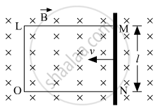
A rectangular conductor LMNO is placed in a uniform magnetic field of 0.5 T. The field is directed perpendicular to the plane of the conductor. When the arm MN of length of 20 cm is moved towards left with a velocity of 10 ms−1, calculate the emf induced in the arm. Given the resistance of the arm to be 5 Ω (assuming that other arms are of negligible resistance) find the value of the current in the arm.

A cell of emf E and internal resistance r is connected to two external resistance R1 and R2 and a perfect ammeter. The current in the circuit is measured in four different situations:
(i) without any external resistance in the circuit
(ii) with resistance R1 only
(iii) with R1 and R2 in series combination
(iv) with R1 and R2 in parallel combination
The currents measured in the four cases are 0.42 A, 1.05 A, 1.4 A and 4.2 A, but not necessarily in the order. Identify the currents corresponding to the four cases mentioned above.
Find the equivalent resistance of the network shown in the figure between the points a and b.

Do all thermocouples have a neutral temperature?
A plate of area 10 cm2 is to be electroplated with copper (density 9000 kg m−3) to a thickness of 10 micrometres on both sides, using a cell of 12 V. Calculate the energy spent by the cell in the process of deposition. If this energy is used to heat 100 g of water, calculate the rise in the temperature of the water. ECE of copper = 3 × 10⁻⁷ kg C−1and specific heat capacity of water = 4200 J kg−1.
Answer the following question.
What is the end error in a meter bridge? How is it overcome? The resistances in the two arms of the metre bridge are R = Ω and S respectively. When the resistance S is shunted with equal resistance, the new balance length found to be 1.5 l1, where l2 is the initial balancing length. calculate the value of s.

A conductor of length 'l' is rotated about one of its ends at a constant angular speed 'ω' in a plane perpendicular to a uniform magnetic field B. Plot graphs to show variations of the emf induced across the ends of the conductor with (i) angular speed ω and (ii) length of the conductor l.
If n cells each of emf e and internal resistance r are connected in parallel, then the total emf and internal resistance will be ______.
