Advertisements
Advertisements
प्रश्न
A battery of emf 100 V and a resistor of resistance 10 kΩ are joined in series. This system is used as a source to supply current to an external resistance R. If R is not greater than 100 Ω, the current through it is constant up to two significant digits.
Find its value. This is the basic principle of a constant-current source.
उत्तर
Given:-
Emf of the battery, E = 100 volt
Resistance in series with battery, R' = 10 kΩ = 10000 Ω
External resistance, R = (1-100) Ω
When no external resistor is present (R = 0), current through the circuit,
\[i = \frac{E}{R'} = \frac{100}{1000} = 0 . 01 \text{ Amp.}\]
When R = 1 Ω,
\[i = \frac{100}{10000 + 1} = \frac{100}{10001}\]
\[ = 0 . 009999 A\]
When R = 100 Ω,
\[i = \frac{100}{10000 + 100}\]
\[ = \frac{100}{10100} = 0 . 009900 A\]
We can see that up to R = 100 Ω, the current does not change up to two significant digits.
APPEARS IN
संबंधित प्रश्न
Two identical cells of emf 1.5 V each joined in parallel, supply energy to an external circuit consisting of two resistances of 7 Ω each joined in parallel. A very high resistance voltmeter reads the terminal voltage of cells to be 1.4 V. Calculate the internal resistance of each cell.
A cell of emf 'E' and internal resistance 'r' is connected across a variable load resistor R. Draw the plots of the terminal voltage V versus (i) R and (ii) the current I.
It is found that when R = 4 Ω, the current is 1 A and when R is increased to 9 Ω, the current reduces to 0.5 A. Find the values of the emf E and internal resistance r.
A cell of emf 'E' and internal resistance 'r' is connected across a variable resistor 'R'. Plot a graph showing variation of terminal voltage 'V' of the cell versus the current 'I'. Using the plot, show how the emf of the cell and its internal resistance can be determined.
Nichrome and copper wires of same length and same radius are connected in series. Current I is passed through them. Which wire gets heated up more? Justify your answer.
Plot a graph showing variation of voltage vs the current drawn from the cell. How can one get information from this plot about the emf of the cell and its internal resistance?
Two identical cells, each of emf E, having negligible internal resistance, are connected in parallel with each other across an external resistance R. What is the current through this resistance?
Two cells of emf E1, E2 and internal resistance r1 and r2 respectively are connected in parallel as shown in the figure.

Deduce the expressions for
(1) the equivalent e.m.f of the combination
(2) the equivalent resistance of the combination, and
(3) the potential difference between the point A and B.
Can the potential difference across a battery be greater than its emf?
Two non-ideal batteries are connected in parallel. Consider the following statements:-
(A) The equivalent emf is smaller than either of the two emfs.
(B) The equivalent internal resistance is smaller than either of the two internal resistances.
Find the value of i1/i2 in the following figure if (a) R = 0.1 Ω (b) R = 1 Ω and (c) R = 10 Ω. Note from your answers that in order to get more current from a combination of two batteries, they should be joined in parallel if the external resistance is small and in series if the external resistance is large, compared to the internal resistance.

The temperatures of the junctions of a bismuth-silver thermocouple are maintained at 0°C and 0.001°C. Find the thermo-emf (Seebeck emf) developed. For bismuth-silver, a = − 46 × 10−6 V°C−1 and b = −0.48 × 10⁻⁶ V°C−2.
Answer the following question.
A cell of emf E and internal resistance r is connected across a variable resistor R. Plot the shape of graphs showing a variation of terminal voltage V with (i) R and (ii) circuit current I.
A conductor of length 'l' is rotated about one of its ends at a constant angular speed 'ω' in a plane perpendicular to a uniform magnetic field B. Plot graphs to show variations of the emf induced across the ends of the conductor with (i) angular speed ω and (ii) length of the conductor l.
Two cells of emfs approximately 5 V and 10 V are to be accurately compared using a potentiometer of length 400 cm.
A cell having an emf E and internal resistance r is connected across a variable external resistance R. As the resistance R is increased, the plot of potential difference V across R is given by ______.
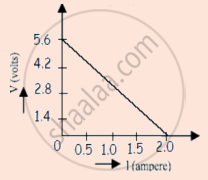
A straight line plot showing the terminal potential difference (V) of a cell as a function of current (I) drawn from it, is shown in the figure. The internal resistance of the cell would be then ______.

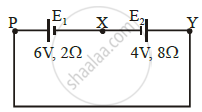
A cell E1 of emf 6 V and internal resistance 2 Ω is connected with another cell E2 of emf 4 V and internal resistance 8 Ω (as shown in the figure). The potential difference across points X and Y is ______.

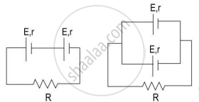
Study the two circuits shown in the figure below. The cells in the two circuits are identical to each other. The resistance of the load resistor R is the same in both circuits.

If the same current flows through the resistor R in both circuits, calculate the internal resistance of each cell in terms of the resistance of resistor R. Show your calculations.
