Advertisements
Online Mock Tests
Chapters
2: Kinetic Theory of Gases
3: Calorimetry
4: Laws of Thermodynamics
5: Specific Heat Capacities of Gases
6: Heat Transfer
7: Electric Field and Potential
8: Gauss’s Law
9: Capacitors
▶ 10: Electric Current in Conductors
11: Thermal and Chemical Effects of Current
12: Magnetic Field
13: Magnetic Field due to a Current
14: Permanent Magnets
15: Magnetic Properties of Matter
16: Electromagnetic Induction
17: Alternating Current
18: Electromagnetic Waves
19: Electric Current through Gases
20: Photoelectric Effect and Wave-Particle Duality
21: Bohr’s Model and Physics of Atom
22: X-rays
23: Semiconductors and Semiconductor Devices
24: The Nucleus
25: The Special Theory of Relativity
![HC Verma solutions for Concepts of Physics Vol. 2 [English] Class 11 and 12 chapter 10 - Electric Current in Conductors - Shaalaa.com](/images/9788177092325-concepts-of-physics-vol-2-english-class-11-and-12_6:cd4e4bfcb8474a60871d8e5659ec4eb9.jpg "HC Verma solutions for Concepts of Physics Vol. 2 [English] Class 11 and 12 chapter 10 - Electric Current in Conductors")
Advertisements
Solutions for Chapter 10: Electric Current in Conductors
Below listed, you can find solutions for Chapter 10 of CBSE, Karnataka Board PUC HC Verma for Concepts of Physics Vol. 2 [English] Class 11 and 12.
HC Verma solutions for Concepts of Physics Vol. 2 [English] Class 11 and 12 10 Electric Current in Conductors Short Answers [Page 196]
Suppose you have three resistors, each of value 30 Ω. List all the different resistances you can obtain using them.
A proton beam is moving from east to west. Is there an electric current? If yes, in what direction?
In an electrolyte, the positive ions move from left to right and the negative ions from right to left. Is there a net current? If yes, in what direction?
In a TV tube, electrons are accelerated from the rear to the front. What is the direction of the current?
Drift speed is defined as vd = Δl/Δt, where Δl is the distance drifted in a long time Δt. Why don't we define drift speed as the limit of Δl/Δt as Δt → 0?
One of your friends says that he has read in the previous chapters that there can be no electric field inside a conductor. Consequently, there can be no current through it. What is the fallacy of this argument?
When a current is established in a wire, the free electrons drift in the direction opposite to the current. Does the number of free electrons in the wire continuously decrease?
A fan with copper winding in its motor consumes less power compared to a similar fan with aluminium winding. Explain.
The thermal energy developed in a current-carrying resistor is given by U = i2 Rt and also by U = Vit. Should we say that U is proportional to i2 or i?
Consider a circuit containing an ideal battery connected to a resistor. Do "work done by the battery" and "the thermal energy developed" represent two names of the same physical quantity?
Is work done by a battery always equal to the thermal energy developed in electrical circuit? What happens if a capacitor is connected in the circuit?
A non-ideal battery is connected to a resistor. Is work done by the battery equal to the thermal energy developed in the resistor? Will your answer change if the battery is ideal?
Sometimes it is said that "heat is developed" in a resistance when there is an electric current in it. Recall that heat is defined as the energy being transferred due to temperature difference. Is the statement in quotes technically correct?
We often say, "A current is going through the wire." What goes through the wire, the charge or the current?
Would you prefer a voltmeter or a potentiometer to measure the emf of a battery?
Does a conductor become charged when a current is passed through it?
Can the potential difference across a battery be greater than its emf?
HC Verma solutions for Concepts of Physics Vol. 2 [English] Class 11 and 12 10 Electric Current in Conductors MCQ [Pages 196 - 197]
A metallic resistor is connected across a battery. If the number of collisions of the free electrons with the lattice is somehow decreased in the resistor (for example, by cooling it), the current will ____________ .
increase
decrease
remain constant
become zero
Two resistors A and B have resistances RA and RB, respectively, and RA < RB. The resistivities of their materials are ρA and ρB.
ρA > ρB
ρA = ρB
ρA < ρB
The information is not sufficient to find the relation between ρA and ρB
The product of resistivity and conductivity of a cylindrical conductor depends on ____________ .
temperature
material
area of cross section
None of these
As the temperature of a metallic resistor is increased, the product of its resistivity and conductivity ____________ .
increases
decreases
remains constant
may increase or decrease
In an electric circuit containing a battery, the charge (assumed positive) inside the battery ____________ .
always goes from the positive terminal to the negative terminal
may go from the positive terminal to the negative terminal
always goes from the negative terminal to the positive terminal
does not move
A resistor of resistance R is connected to an ideal battery. If the value of R is decreased, the power dissipated in the resistor will ______________ .
increase
decrease
remain unchanged
A current passes through a resistor. Let K1 and K2 represent the average kinetic energy of the conduction electrons and the metal ions, respectively.
K2 < K2
K1 = K2
K1 > K2
Any of these three may occur
Two resistors R and 2R are connected in series in an electric circuit. The thermal energy developed in R and 2R are in the ratio ______________ .
1 : 2
2 : 1
1 : 4
4 : 1
Two resistances R and 2R are connected in parallel in an electric circuit. The thermal energy developed in R and 2R are in the ratio _______________ .
1 : 2
2 : 1
1 : 4
4 : 1
A uniform wire of resistance 50 Ω is cut into 5 equal parts. These parts are now connected in parallel. The equivalent resistance of the combination is ______________ .
2 Ω
10 Ω
250 Ω
6250 Ω
Consider the following two statements:-
(A) Kirchhoff's junction law follows from conservation of charge.
(B) Kirchhoff's loop law follows from conservative nature of electric field.
A and B are correct
A is correct but B is wrong
B is correct but A is wrong
A and B are wrong
Two non-ideal batteries are connected in series. Consider the following statements:-
(A) The equivalent emf is larger than either of the two emfs.
(B) The equivalent internal resistance is smaller than either of the two internal resistances.
A and B are correct
A is correct but B is wrong
B is correct but A is wrong
A and B are wrong
Two non-ideal batteries are connected in parallel. Consider the following statements:-
(A) The equivalent emf is smaller than either of the two emfs.
(B) The equivalent internal resistance is smaller than either of the two internal resistances.
A and B are correct
A is correct but B is wrong
B is correct but A is wrong
A and B are wrong
The net resistance of an ammeter should be small to ensure that _______________ .
it does not get overheated
it does not draw excessive current
it can measure large currents
it does not appreciably change the current to be measured
The net resistance of a voltmeter should be large to ensure that ______________ .
it does not get overheated
it does not draw excessive current
it can measure large potential differences
it does not appreciably change the potential difference to be measured
Consider a capacitor-charging circuit. Let Q1 be the charge given to the capacitor in a time interval of 10 ms and Q2 be the charge given in the next time interval of 10 ms. Let 10 μC charge be deposited in time interval t1 and another 10 μC charge be deposited in the next time interval t2.
Q1 > Q2, t1 > t2
Q1 > Q2, t1 < t2
Q1 < Q2, t1 > t2
Q1 < Q2, t1 < t2
HC Verma solutions for Concepts of Physics Vol. 2 [English] Class 11 and 12 10 Electric Current in Conductors MCQ [Pages 197 - 198]
Electrons are emitted by a hot filament and are accelerated by an electric field, as shown in the figure. The two stops at the left ensure that the electron beam has a uniform cross-section.
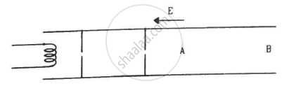
The speed of the electrons is more at B than at A
The electric current is from left to right
The magnitude of the current is larger at B than at A
The current density is more at B than at A
A capacitor with no dielectric is connected to a battery at t = 0. Consider a point A in the connecting wires and a point B between the plates.
(a) There is no current through A.
(b) There is no current through B.
(c) There is a current through A as long as the charging is not complete.
(d) There is a current through B as long as the charging is not complete.
When no current is passed through a conductor, ______.
the free electrons do not move.
the average speed of a free electron over a large period of time is zero.
the average velocity of a free electron over a large period of time is zero.
the average of the velocities of all the free electrons at an instant is zero.
Which of the following quantities does not change when a resistor connected to a battery is heated due to the current?
Drift speed
Resistivity
Resistance
Number of free electrons
As the temperature of a conductor increases, its resistivity and conductivity change. The ratio of resistivity to conductivity _______________ .
increases
decreases
remains constant
may increase or decrease, depending on the actual temperature
A current passes through a wire of non-uniform cross-section. Which of the following quantities are independent of the cross-section?
(a) The charge crossing in a given time interval
(b) Drift speed
(c) Current density
(d) Free-electron density
Identify the correct options.
(a) An ammeter should have small resistance.
(b) An ammeter should have large resistance.
(c) A voltmeter should have small resistance.
(d) A voltmeter should have large resistance.
A capacitor of capacitance 500 μF is connected to a battery through a 10 kΩ resistor. The charge stored in the capacitor in the first 5 s is larger than the charge stored in the next.
(a) 5 s
(b) 50 s
(c) 500 s
(d) 500 s
A capacitor C1 of capacitance 1 μF and a capacitor C2 of capacitance 2 μF are separately charged by a common battery for a long time. The two capacitors are then separately discharged through equal resistors. Both the discharge circuits are connected at t = 0.
(a) The current in each of the two discharging circuits is zero at t = 0.
(b) The currents in the two discharging circuits at t = 0 are equal but not zero.
(c) The currents in the two discharging circuits at t = 0 are unequal.
(d) C1 loses 50% of its initial charge sooner than C2 loses 50% of its initial charge.
HC Verma solutions for Concepts of Physics Vol. 2 [English] Class 11 and 12 10 Electric Current in Conductors Exercises [Pages 198 - 203]
The amount of charge that passes in time t through a cross-section of a wire is
Q(t) = At2 + Bt + C.
(a) Write the dimensional formulae for A, B and C.
(b) If the numerical values of A, B and C are 5, 3 and 1, respectively, in S.I units, find the value of the current at t = 5 s.
An electron gun emits 2.0 ×10¹⁶ electrons per second. What electric current does this correspond to?
The electric current existing in a discharge tube is 2.0 μA. How much charge is transferred across a cross-section of the tube in 5 minutes?
The current through a wire depends on time as i = i0 + αt, where i0 = 10 A and α = 4 As–1. Find the charge that crosses through a section of the wire in 10 seconds.
A current of 1.0 A exists in a copper wire of cross-section 1.0 mm2. Assuming one free electron per atom, calculate the drift speed of the free electrons in the wire. The density of copper is 9000 kg m–3.
A wire of length 1 m and radius 0.1 mm has a resistance of 100 Ω. Find the resistivity of the material.
A uniform wire of resistance 100 Ω is melted and recast as a wire whose length is double that of the original. What would be the resistance of the wire?
Consider a wire of length 4 m and cross-sectional area 1 mm2 carrying a current of 2 A. If each cubic metre of the material contains 1029 free electrons, find the average time taken by an electron to cross the length of the wire.
What length of a copper wire of cross-sectional area 0.01 mm2 will be needed to prepare a resistance of 1 kΩ? Resistivity of copper = 1.7 × 10⁻⁸ Ωm
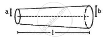
The following figure shows a conductor of length l with a circular cross-section. The radius of the cross-section varies linearly from a to b. The resistivity of the material is ρ. Assuming that b – a << l, find the resistance of the conductor.
A copper wire of radius 0.1 mm and resistance kΩ is connected across a power supply of 20 V. (a) How many electrons are transferred per second between the supply and the wire at one end? (b) Write down the current density in the wire.
Calculate the electric field in a copper wire of cross-sectional area 2.0 mm2 carrying a current of 1 A.
The resistivity of copper = 1.7 × 10⁻⁸ Ω m
A wire has a length of 2.0 m and a resistance of 5.0 Ω. Find the electric field existing inside the wire if it carries a current of 10 A.
The resistance of an iron wire and a copper wire at 20°C are 3.9 Ω and 4.1 Ω, respectively. At what temperature will the resistance be equal? Temperature coefficient of resistivity for iron is 5.0 × 10⁻³ K–1 and for copper, it is 4.0 × 10⁻³ K–1. Neglect any thermal expansion.
The current in a conductor and the potential difference across its ends are measured by an ammeter and a voltmeter. The meters draw negligible currents. The ammeter is accurate but the voltmeter has a zero error (that is, it does not read zero when no potential difference is applied). Calculate the zero error if the readings for two different conditions are 1.75 A, 14.4 V and 2.75 A, 22.4 V.
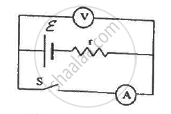
The following figure shows an arrangement to measure the emf ε and internal resistance r of a battery. The voltmeter has a very high resistance and the ammeter also has some resistance. The voltmeter reads 1.52 V when the switch S is open. When the switch is closed, the voltmeter reading drops to 1.45 V and the ammeter reads 1.0 A. Find the emf and the internal resistance of the battery.
The potential difference between the terminals of a battery of emf 6.0 V and internal resistance 1 Ω drops to 5.8 V when connected across an external resistor. Find the resistance of the external resistor.
The potential difference between the terminals of a 6.0 V battery is 7.2 V when it is being charged by a current of 2.0 A. What is the internal resistance of the battery?
The internal resistance of an accumulator battery of emf 6 V is 10 Ω when it is fully discharged. As the battery gets charged up, its internal resistance decreases to 1 Ω.
The battery in its completely discharged state is connected to a charger that maintains a constant potential difference of 9 V. Find the current through the battery (a) just after the connections are made and (b) after a long time when it is completely charged.
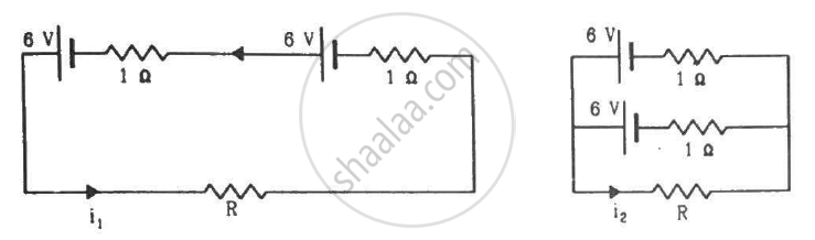
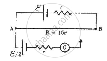
Find the value of i1/i2 in the following figure if (a) R = 0.1 Ω (b) R = 1 Ω and (c) R = 10 Ω. Note from your answers that in order to get more current from a combination of two batteries, they should be joined in parallel if the external resistance is small and in series if the external resistance is large, compared to the internal resistance.
Consider N = n1n2 identical cells, each of emf ε and internal resistance r. Suppose n1 cells are joined in series to form a line and n2 such lines are connected in parallel.
The combination drives a current in an external resistance R. (a) Find the current in the external resistance. (b) Assuming that n1 and n2 can be continuously varied, find the relation between n1, n2, R and r for which the current in R is maximum.
A battery of emf 100 V and a resistor of resistance 10 kΩ are joined in series. This system is used as a source to supply current to an external resistance R. If R is not greater than 100 Ω, the current through it is constant up to two significant digits.
Find its value. This is the basic principle of a constant-current source.
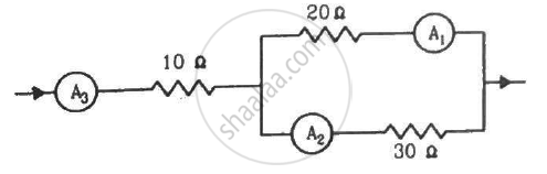
If the reading of the ammeter, A1 in the following figure is 2.4 A, what will be the readings of ammeters A2 and A3? Neglect the resistances of the ammeters.
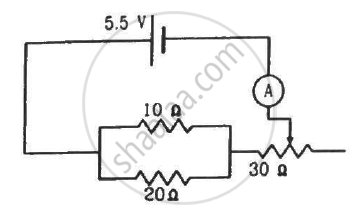
The resistance of the rheostat shown in the figure is 30 Ω. Neglecting the meter resistance, find the minimum and maximum currents through the ammeter as the rheostat is varied.
Three bulbs, each with a resistance of 180 Ω, are connected in parallel to an ideal battery of emf 60 V.
Find the current delivered by the battery when (a) all the bulbs are switched on, (b) two of the bulbs are switched on and (c) only one bulb is switched on.
Suppose you have three resistors of 20 Ω, 50 Ω and 100 Ω. What minimum and maximum resistance can you obtain from these resistors?
A bulb is made using two filaments. A switch selects whether the filaments are used individually or in parallel. When used with a 15 V battery, the bulb can be operated at 5 W, 10 W or 15 W. What should be the resistances of the filaments?
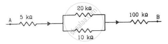
The following figure shows a part of a circuit. If a current of 12 mA exists in the 5 kΩ resistor, find the currents in the other three resistors. What is the potential difference between the points A and B?
An ideal battery sends a current of 5 A in a resistor. When another resistor of 10 Ω is connected in parallel, the current through the battery is increased to 6 A. Find the resistance of the first resistor.
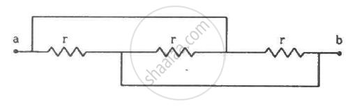
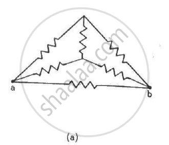
Find the equivalent resistance of the network shown in the figure between the points a and b.
A wire of resistance 15.0 Ω is bent to form a regular hexagon ABCDEFA. Find the equivalent resistance of the loop between the points (a) A and B (b) A and C and (c) Aand D.
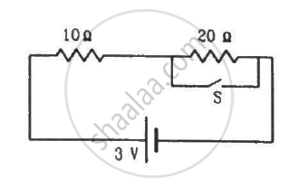
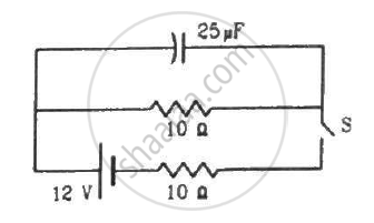
Consider the circuit shown in the figure. Find the current through the 10 Ω resistor when the switch S is (a) open (b) closed.
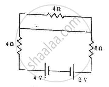
Find the currents through the three resistors shown in the figure.
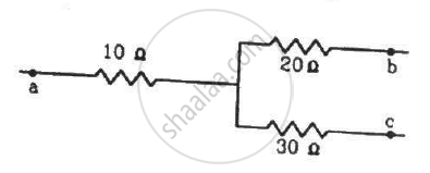
The following figure shows a part of an electric circuit. The potentials at the points a, b and care 30 V, 12 V and 2 V respectively. Find the currents through the three resistors.
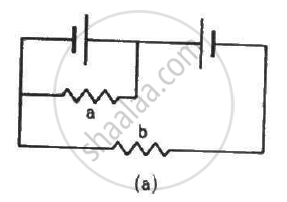
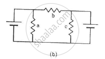
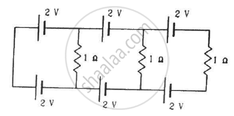
Each of the resistors shown in the figure has a resistance of 10 Ω and each of the batteries has an emf of 10 V. Find the currents flowing through the resistors a and bin the two circuits.
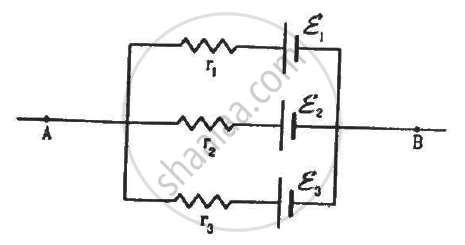
Find the potential difference Va – Vb in the circuits shown in the figure.
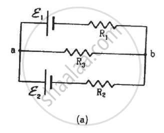
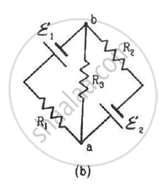
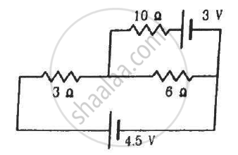
In the circuit shown in the figure, ε1 = 3 V, ε2 = 2 V, εa = 1 V and r1 = r2 = r3 = 1Ω. Find the potential difference between the points A and B and the current through each branch.
Find the current through the 10 Ω resistor shown in the figure.
Find the circuit in the three resistors shown in the figure.
What should be the value of R in the figure for which the current in it is zero?
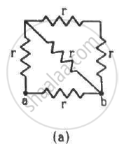
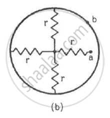
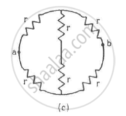
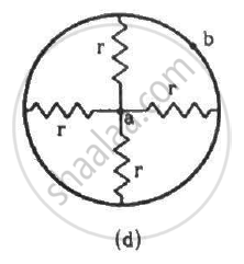
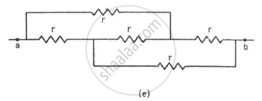
Find the equivalent resistance of the circuits shown in the figure between the points a and b. Each resistor has resistance r.

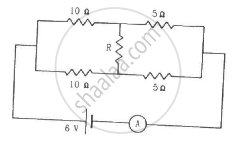
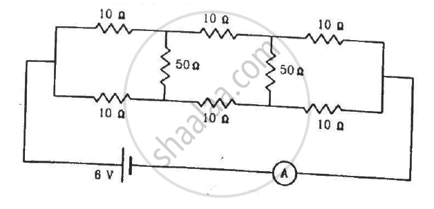
Find the current measured by the ammeter in the circuit shown in the figure.
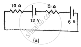
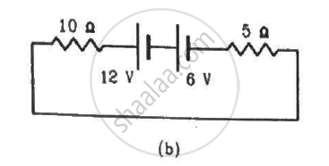
Consider the circuit shown in the figure. Find (a) the current in the circuit (b) the potential drop across the 5 Ω resistor (c) the potential drop across the 10 Ω resistor (d) Answer the parts (a), (b) and (c) with reference to the figure.
Twelve wires, each of equal resistance r, are joined to form a cube, as shown in the figure. Find the equivalent resistance between the diagonally-opposite points a and f.

Find the equivalent resistances of the networks shown in the figure between the points a and b.
An infinite ladder is constructed with 1 Ω and 2 Ω resistors, as shown in the figure. (a) Find the effective resistance between the points A and B. (b) Find the current that passes through the 2 Ω resistor nearest to the battery.

The emf ε and the internal resistance r of the battery, shown in the figure, are 4.3 V and 1.0 Ω respectively. The external resistance R is 50 Ω. The resistances of the ammeter and voltmeter are 2.0 Ω and 200 Ω respectively. (a) Find the readings of the two meters. (b) The switch is thrown to the other side. What will be the readings of the two meters now?

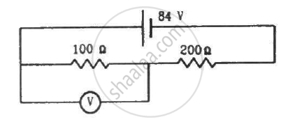
A voltmeter of resistance 400 Ω is used to measure the potential difference across the 100 Ω resistor in the circuit shown in the figure. (a) What will be the reading of the voltmeter? (b) What was the potential difference across 100 Ω before the voltmeter was connected?
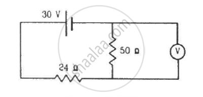
The voltmeter shown in the figure reads 18 V across the 50 Ω resistor. Find the resistance of the voltmeter.
A voltmeter consists of a 25 Ω coil connected in series with a 575 Ω resistor. The coil takes 10 mA for full-scale deflection. What maximum potential difference can be measured by this voltmeter?
An ammeter is to be constructed that can read currents up to 2.0 A. If the coil has resistance of 25 Ω and takes 1 mA for full-scale deflection, what should be the resistance of the shunt used?
A voltmeter coil has resistance 50.0 Ω and a resistor of 1.15 kΩ is connected in series. It can read potential differences up to 12 volts. If this same coil is used to construct an ammeter that can measure currents up to 2.0 A, what should be the resistance of the shunt used?
The potentiometer wire AB shown in the figure is 40 cm long. Where should the free end of the galvanometer be connected on AB, so that the galvanometer may show zero deflection?

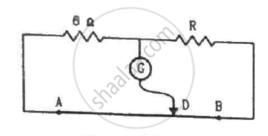
The potentiometer wire AB shown in the figure is 50 cm long. When AD = 30 cm, no deflection occurs in the galvanometer. Find R.
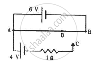
A 6-volt battery of negligible internal resistance is connected across a uniform wire AB of length 100 cm. The positive terminal of another battery of emf 4 V and internal resistance 1 Ω is joined to the point A, as shown in the figure. Take the potential at B to be zero. (a) What are the potentials at the points A and C? (b) At which point D of the wire AB, the potential is equal to the potential at C? (c) If the points C and D are connected by a wire, what will be the current through it? (d) If the 4 V battery is replaced by a 7.5 V battery, what would be the answers of parts (a) and (b)?
Consider the potentiometer circuit as arranged in the figure. The potentiometer wire is 600 cm long. (a) At what distance from the point A should the jockey touch the wire to get zero deflection in the galvanometer? (b) If the jockey touches the wire at a distance of 560 cm from A, what will be the current in the galvanometer?
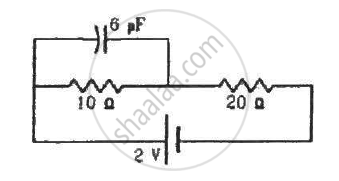
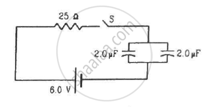
Find the charge on the capacitor shown in the figure.
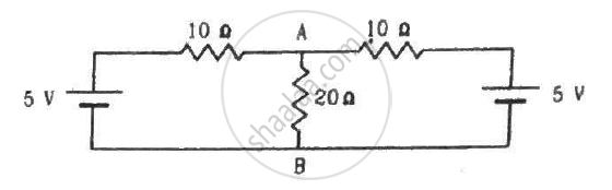
(a) Find the current in the 20 Ω resistor shown in the figure. (b) If a capacitor of capacitance 4 μF is joined between the points A and B, what would be the electrostatic energy stored in it in steady state?
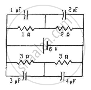
Find the charges on the four capacitors of capacitances 1 μF, 2 μF, 3 μF and 4 μF shown in the figure.
Find the potential difference between the points A and B and between the points B and C of the figure in steady state.

A capacitance C, a resistance R and an emf ε are connected in series at t = 0. What is the maximum value of (a) the potential difference across the resistor (b) the current in the circuit (c) the potential difference across the capacitor (d) the energy stored in the capacitor (e) the power delivered by the battery and (f) the power converted into heat?
A parallel-plate capacitor with plate area 20 cm2 and plate separation 1.0 mm is connected to a battery. The resistance of the circuit is 10 kΩ. Find the time constant of the circuit.
A capacitor of capacitance 10 μF is connected to a battery of emf 2 V. It is found that it takes 50 ms for the charge of the capacitor to become 12.6 μC. Find the resistance of the circuit.
A 20 μF capacitor is joined to a battery of emf 6.0 V through a resistance of 100 Ω. Find the charge on the capacitor 2.0 ms after the connections are made.
The plates of a capacitor of capacitance 10 μF, charged to 60 μC, are joined together by a wire of resistance 10 Ω at t = 0. Find the charge on the capacitor in the circuit at (a) t = 0 (b) t = 30 μs (c) t = 120 μs and (d) t = 1.0 ms.
A capacitor of capacitance 8.0 μF is connected to a battery of emf 6.0 V through a resistance of 24 Ω. Find the current in the circuit (a) just after the connections are made and (b) one time constant after the connections are made.
A parallel-plate capacitor of plate area 40 cm2 and separation between the plates 0.10 mm, is connected to a battery of emf 2.0 V through a 16 Ω resistor. Find the electric field in the capacitor 10 ns after the connections are made.
A parallel-plate capacitor has plate area 20 cm2, plate separation 1.0 mm and a dielectric slab of dielectric constant 5.0 filling up the space between the plates. This capacitor is joined to a battery of emf 6.0 V through a 100 kΩ resistor. Find the energy of the capacitor 8.9 μs after the connections are made.
A 100 μF capacitor is joined to a 24 V battery through a 1.0 MΩ resistor. Plot qualitative graphs (a) between current and time for the first 10 minutes and (b) between charge and time for the same period.
How many time constants will elapse before the current in a charging RC circuit drops to half of its initial value? Answer the same question for a discharging RC circuit.
How many time constants will elapse before the charge on a capacitors falls to 0.1% of its maximum value in a discharging RC circuit?
How many time constants will elapse before the energy stored in the capacitor reaches half of its equilibrium value in a charging RC circuit?
How many time constants will elapse before the power delivered by a battery drops to half of its maximum value in an RC circuit?
A capacitor of capacitance C is connected to a battery of emf ε at t = 0 through a resistance R. Find the maximum rate at which energy is stored in the capacitor. When does the rate have this maximum value?
A capacitor of capacitance 12.0 μF is connected to a battery of emf 6.00 V and internal resistance 1.00 Ω through resistanceless leads. 12.0 μs after the connections are made, what will be (a) the current in the circuit (b) the power delivered by the battery (c) the power dissipated in heat and (d) the rate at which the energy stored in the capacitor is increasing?
A capacitance C charged to a potential difference V is discharged by connecting its plates through a resistance R. Find the heat dissipated in one time constant after the connections are made. Do this by calculating ∫ i2R dt and also by finding the decrease in the energy stored in the capacitor.
By evaluating ∫i2Rdt, show that when a capacitor is charged by connecting it to a battery through a resistor, the energy dissipated as heat equals the energy stored in the capacitor.
A parallel-plate capacitor is filled with a dielectric material of resistivity ρ and dielectric constant K. The capacitor is charged and disconnected from the charging source. The capacitor is slowly discharged through the dielectric. Show that the time constant of the discharge is independent of all geometrical parameters like the plate area or separation between the plates. Find this time constant.
Find the charge on each of the capacitors 0.20 ms after the switch S is closed in the figure.
The switch S shown in figure is kept closed for a long time and is then opened at t = 0. Find the current in the middle 10 Ω resistor at t = 1 ms.
A capacitor of capacitance 100 μF is connected across a battery of emf 6 V through a resistance of 20 kΩ for 4 s. The battery is then replaced by a thick wire. What will be the charge on the capacitor 4 s after the battery is disconnected?
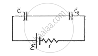
Consider the situation shown in figure. The switch is closed at t = 0 when the capacitors are uncharged. Find the charge on the capacitor C1 as a function of time t.
A capacitor of capacitance C is given a charge Q. At t = 0, it is connected to an uncharged capacitor of equal capacitance through a resistance R. Find the charge on the second capacitor as a function of time.
A capacitor of capacitance C is given a charge Q. At t = 0, it is connected to an ideal battery of emf ε through a resistance R. Find the charge on the capacitor at time t.
Solutions for 10: Electric Current in Conductors
HC Verma solutions for Concepts of Physics Vol. 2 [English] Class 11 and 12 chapter 10 - Electric Current in Conductors
Shaalaa.com has the CBSE, Karnataka Board PUC Mathematics Concepts of Physics Vol. 2 [English] Class 11 and 12 CBSE, Karnataka Board PUC solutions in a manner that help students grasp basic concepts better and faster. The detailed, step-by-step solutions will help you understand the concepts better and clarify any confusion. HC Verma solutions for Mathematics Concepts of Physics Vol. 2 [English] Class 11 and 12 CBSE, Karnataka Board PUC 10 (Electric Current in Conductors) include all questions with answers and detailed explanations. This will clear students' doubts about questions and improve their application skills while preparing for board exams.
Further, we at Shaalaa.com provide such solutions so students can prepare for written exams. HC Verma textbook solutions can be a core help for self-study and provide excellent self-help guidance for students.
Concepts covered in Concepts of Physics Vol. 2 [English] Class 11 and 12 chapter 10 Electric Current in Conductors are Combination of Capacitors, Capacitors and Capacitance, Dielectrics and Polarisation, Free Charges and Bound Charges Inside a Conductor, Conductors and Insulators Related to Electric Field, Electrical Potential Energy of a System of Two Point Charges and of Electric Dipole in an Electrostatic Field, Equipotential Surfaces, Potential Due to a System of Charges, Electric Potential Difference, Potential Due to a Point Charge, Electric Potential, Van De Graaff Generator, Effect of Dielectric on Capacity, The Parallel Plate Capacitor, Electrostatics of Conductors, Potential Energy of a Dipole in an External Field, Potential Energy of a System of Two Charges in an External Field, Potential Energy of a Single Charge, Potential Energy of a System of Charges, Potential Due to an Electric Dipole, Relation Between Electric Field and Electrostatic Potential, Energy Stored in a Capacitor, Capacitance of a Parallel Plate Capacitor with and Without Dielectric Medium Between the Plates, Limitations of Ohm’s Law, Electric Currents in Conductors, Conductivity and Conductance;, Current Density, Delta Star Transformation, Potential Difference and Emf of a Cell, Measurement of Internal Resistance of a Cell, Potentiometer, Metre Bridge, Wheatstone Bridge, Kirchhoff’s Rules, Combination of Cells in Series and in Parallel, Cells, Emf, Internal Resistance, Temperature Dependence of Resistance, Combination of Resistors - Series and Parallel, Resistivity of Various Materials, Drift of Electrons and the Origin of Resistivity, Ohm's Law (V = IR), Electric Current, Electrical Power, Electrical Resistivity and Conductivity, V-I Characteristics (Linear and Non-linear), Flow of Electric Charges in a Metallic Conductor.
Using HC Verma Concepts of Physics Vol. 2 [English] Class 11 and 12 solutions Electric Current in Conductors exercise by students is an easy way to prepare for the exams, as they involve solutions arranged chapter-wise and also page-wise. The questions involved in HC Verma Solutions are essential questions that can be asked in the final exam. Maximum CBSE, Karnataka Board PUC Concepts of Physics Vol. 2 [English] Class 11 and 12 students prefer HC Verma Textbook Solutions to score more in exams.
Get the free view of Chapter 10, Electric Current in Conductors Concepts of Physics Vol. 2 [English] Class 11 and 12 additional questions for Mathematics Concepts of Physics Vol. 2 [English] Class 11 and 12 CBSE, Karnataka Board PUC, and you can use Shaalaa.com to keep it handy for your exam preparation.
