Advertisements
Advertisements
प्रश्न
Draw a schematic diagram and explain the working of Van de Graff generator device.
उत्तर

It consists of a large spherical conducting shell (S) supported over the insulating pillars. A long narrow belt of insulating material is wound around two pulleys P1 and P2. B1 and B2 are two sharply pointed metal combs. B1 is called the spray comb and B2 is called the collecting comb.
Working − The spray comb is given a positive potential by high tension source. The positive charge gets sprayed on the belt.
As the belt moves and reaches the sphere, a negative charge is induced on the sharp ends of collecting comb B2 and an equal positive charge is induced on the farther end of B2.
This positive charge shifts immediately to the outer surface of S. Due to discharging action of sharp points of B2, the positive charge on the belt is neutralized. The uncharged belt returns down and collects the positive charge from B1, which in turn is collected by B2. This is repeated. Thus, the positive charge on S goes on accumulating. In this way, voltage differences of as much as 6 or 8 million volts (with respect to the ground) can be built up.
APPEARS IN
संबंधित प्रश्न
Distinguish between Conductors and Insulators.
The potential difference applied across a given resistor is altered so that the heat produced per second increases by a factor of 9. By what factor does the applied potential difference change?
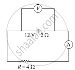
In the figure shown, an ammeter A and a resistor of 4 Ω are connected to the terminals of the source. The emf of the source is 12 V having an internal resistance of 2 Ω. Calculate the voltmeter and ammeter readings.

Is there any restriction on the upper limit of the high voltage set up in Van de Graff generator machine? Explain.
A 100 pF capacitor is charged to a potential difference of 24 V. It is connected to an uncharged capacitor of capacitance 20 pF. What will be the new potential difference across the 100 pF capacitor?
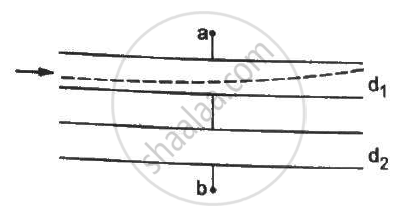
Both the capacitors shown in figure are made of square plates of edge a. The separations between the plates of the capacitors are d1 and d2 as shown in the figure. A potential difference V is applied between the points a and b. An electron is projected between the plates of the upper capacitor along the central line. With what minimum speed should the electron be projected so that it does not collide with any plate? Consider only the electric forces.

Find the potential difference between the points A and B and between the points B and C of the figure in steady state.

A capacitor having a capacitance of 100 µF is charged to a potential difference of 50 V. (a) What is the magnitude of the charge on each plate? (b) The charging battery is disconnected and a dielectric of dielectric constant 2⋅5 is inserted. Calculate the new potential difference between the plates. (c) What charge would have produced this potential difference in absence of the dielectric slab. (d) Find the charge induced at a surface of the dielectric slab.
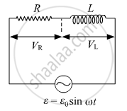
What will be the potential difference in the circuit when direct current is passed through the circuit?

Work done in moving a unit positive charge through a distance of x meter on an equipotential surface is:-
