Advertisements
Advertisements
प्रश्न
Obtain an expression for average power of AC over a cycle. Discuss its special cases.
उत्तर
It is given by the product of the voltage and current. In an AC circuit, the voltage and current vary continuously with time. Let us first calculate the power at an instant and then it is averaged over a complete cycle.
The alternating voltage and alternating current in the series RLC circuit at an instant are given by
υ = Vm sin ωt and i = Im sin (ωt + 4>)
where φ is the phase angle between υ and i. The instantaneous power is then written as
P = υi = Vm Im sin ωt sin(ωt + φ)
= Vm Im sin ωt (sin ωt cos φ – cos ωt sin φ)
P = Vm Im (cos φ sin2 ωt – sin ωt cos ωt sin φ) …… (1)
Here the average of sin2 ωt over a cycle is `1/2` and that of sin ωt cos ωt is zero. Substituting these values, we obtain average power over a cycle.
Pav = Vm Im cos φ `xx 1/2 = "V"_"m"/sqrt2 "I"_"m"/sqrt2` cos φ
Pav = VRMS IRMS cos φ …… (2)
where VRMS IRMS is called apparent power and cos φ is power factor. The average power of an AC circuit is also known as the true power of the circuit.
Special Cases:
- For a purely resistive circuit, the phase angle between voltage and current is zero and cos
φ = 1.
∴ Pav = VRMS IRMS - For a purely inductive or capacitive circuit, the phase angle is
`+- pi/2 and cos (+- pi/2) = 0`
∴ Pav = 0 - For series RLC circuit, the phase angle φ = tan-1 `(("x"_"L" - "x"_"c")/"R")`
∴ Pav = VRMS IRMS cos φ
-
For series RLC circuit at resonance, the phase angle is zero and cos φ = 1.
∴ Pav = VRMS IRMS
APPEARS IN
संबंधित प्रश्न
What are phasors?
What do you mean by resonant frequency?
Predict the polarity of the capacitor in a closed circular loop when two bar magnets are moved as shown in the figure.

The capacitive reactance in an A.C. circuit is ______.
Which of the following graphs represent the variation of current(I) with frequency (f) in an AC circuit containing a pure capacitor?
In an a.c circuit, peak value of voltage is 423 volts, its effective voltage is ______.
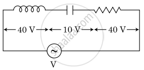
An inductor of inductance L, a capacitor of capacitance C and a resistor of resistance ‘R’ are connected in series to an ac source of potential difference ‘V’ volts as shown in figure. Potential difference across L, C and R is 40 V, 10 V and 40 V, respectively. The amplitude of current flowing through LCR series circuit is `10sqrt2` A. The impedance of the circuit is :

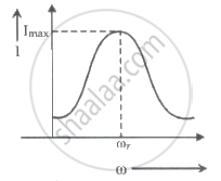
For a series LCR circuit, I vs ω curve is shown:

- To the left of ωr, the circuit is mainly capacitive.
- To the left of ωr, the circuit is mainly inductive.
- At ωr, impedance of the circuit is equal to the resistance of the circuit.
- At ωr, impedance of the circuit is 0.
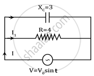
A capacitor and resistor are connected with an AC source as shown in figure. Reactance of capacitor is XC = 3 Ω and resistance of resistor is 4 Ω. Phase difference between current I and I1 is approx ______.

Draw graphs showing the variations of inductive reactance and capacitive reactance with the frequency of the applied ac source.
