Advertisements
Advertisements
Question
Find out the phase relationship between voltage and current in a pure inductive circuit.
Solution
Consider a circuit containing a pure inductor of inductance L connected across an alternating voltage source. The alternating voltage is given by the equation.
υ = Vm sin ωt …(1)
The alternating current flowing through the inductor induces a self-induced emf or back emf in the circuit. The back emf is given by
Back emf, ε -L `"di"/"dt"`
By applying Kirchoff’s loop rule to the purely inductive circuit, we get
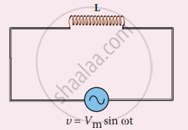
AC circuit with inductor
υ + ε = 0
Vm sin ωt = L`"di"/"dt"`
di = L`"V"_"m"/"L"` sin ωt dt
i = `"V"_"m"/"L" int` sin ωt dt = `"V"_"m"/"L"_omega` (-cos ωt) + constant
The integration constant in the above equation is independent of time. Since the voltage in the circuit has only time dependent part, we can set the time independent part in the current (integration constant) into zero.
`[(cos omega"t" = sin(pi/2 - omega"t")),(- sin (pi/2 - omega"t") = sin (omega"t" - pi/2))]`
i = `"V"_"m"/"L"_omega sin (omega"t" - pi/2) or ` i = `"I"_"m" sin(omega"t" - pi/2)` ....(2)
where `"V"_"m"/"L"_omega = "I"_"m"`, the peak value of the alternating current in the circuit. From equation (1) and (2), it is evident that current lags behind the applied voltage by `pi/2` in an inductive circuit.
This fact is depicted in the phasor diagram. In the wave diagram also, it is seen that current lags the voltage by 90°.
Inductive reactance XL:
The peak value of current Im is given by Im = `"V"_"m"/"L"_omega`. Let us compare this equation with Im = `"V"_"m"/"R"` from resistive circuit. The equantity ωL Plays the same role as the resistance in resistive circuit. This is the resistance offered by the inductor, called inductive reactance (XL). It is measured in ohm.
XL = ωL
The inductive reactance (XL) varies directly as the frequency.
XL = 2πfL …….. (3)
where ƒ is the frequency of the alternating current. For a steady current, ƒ= 0. Therefore, XL = 0. Thus an ideal inductor offers no resistance to steady DC current.

Phasor diagram and wave diagram for AC circuit with L
APPEARS IN
RELATED QUESTIONS
A power transmission line feeds input power at 2200 V to a step-down transformer with its primary windings having 300 turns. Find the number of turns in the secondary to get the power output at 220 V.
The primary coil of an ideal step-up transformer has 100 turns and the transformation ratio is also 100. The input voltage and power are 220 V and 1100 W, respectively. Calculate the
(a) number of turns in secondary
(b) current in the primary
(c) a voltage across secondary
(d) current in secondary
(e) power in secondary
Name two factors on which the magnitude of an induced e.m.f. in the secondary coil depends.
Explain the significance of Lenz’s law to show the conservation of energy in electromagnetic induction.
Can a transformer be used with direct current source? Give reason.
State the factors on which the frequency of the alternating e.m.f. depends.
The power supply to the primary coil of a transformer is 200 W. Find
(i) Current in primary coil if the e.m.f. supply to it is equal to 220V.
(ii) The number of turns in the primary coil is equal to 80 and that in secondary is 800. What is the transformation ratio?
(iii) Name the type of transformer.
(iv) What will be the output voltage?
(v) What is the current in the secondary coil for an ideal transformer?
(vi) What is the output power?
(vii) Is output and input power equal?
(viii) Compare the current flowing in a secondary coil and in a primary coil.
A 200V/120V step-down transformer of 90% efficiency is connected to an induction stove of resistance 40 Ω. Find the current drawn by the primary of the transformer.
Assertion: A transfonner cannot work on D.C. supply.
Reason: D.C. changes neither in magnitude nor in direction.
For what purpose are the transformers used?
